
Contact lens holder

a technology for contact lenses and lenses, which is applied in the field of contact lens holders, can solve the problems of easy protein deposits, difficult installation, and softness of disposable contact lenses, and achieve the effects of easy installation, easy cleaning, and easy cleaning

Inactive Publication Date: 2007-02-20
HUANG JOEY
View PDF9 Cites 75 Cited by
  • Summary
  • Abstract
  • Description
  • Claims
  • Application Information

AI Technical Summary

Benefits of technology

"The patent text discusses a holder assembly for contact lenses that is designed to be more convenient and easy to use. The holder assembly includes a logo cap that can be customized with different logos or advertising messages, and a locking mechanism to secure the cap in place. The holder assembly can be easily detached from the contact lens case for easy cleaning and storage. The technical effects of this invention include improved convenience, easy cleaning and storage, and a more secure and comfortable fit of the contact lens in the eye."

Problems solved by technology

One drawback of contact lenses is its susceptibility to protein deposits.
While it is easy for most users to remove contact lenses, it is much more difficult to install them.
The disposable version of contact lenses is much softer and more difficult to install in the eye.
Also, a person's hands often has irritants such as dust, flaky skin or skin lotion that can irritate the eye.
When a user goes camping or is otherwise traveling, the user may have difficulty finding water to wash hands before installing contact lenses.
Unfortunately, most people do not like to carry too many implements unless they are absolutely necessary.
Although the basket cover offers protection for the contact lens, the entire device still requires manual contact with contact lenses.

Method used


Image

  • Contact lens holder
  • Contact lens holder
  • Contact lens holder

Examples


Embodiment Construction

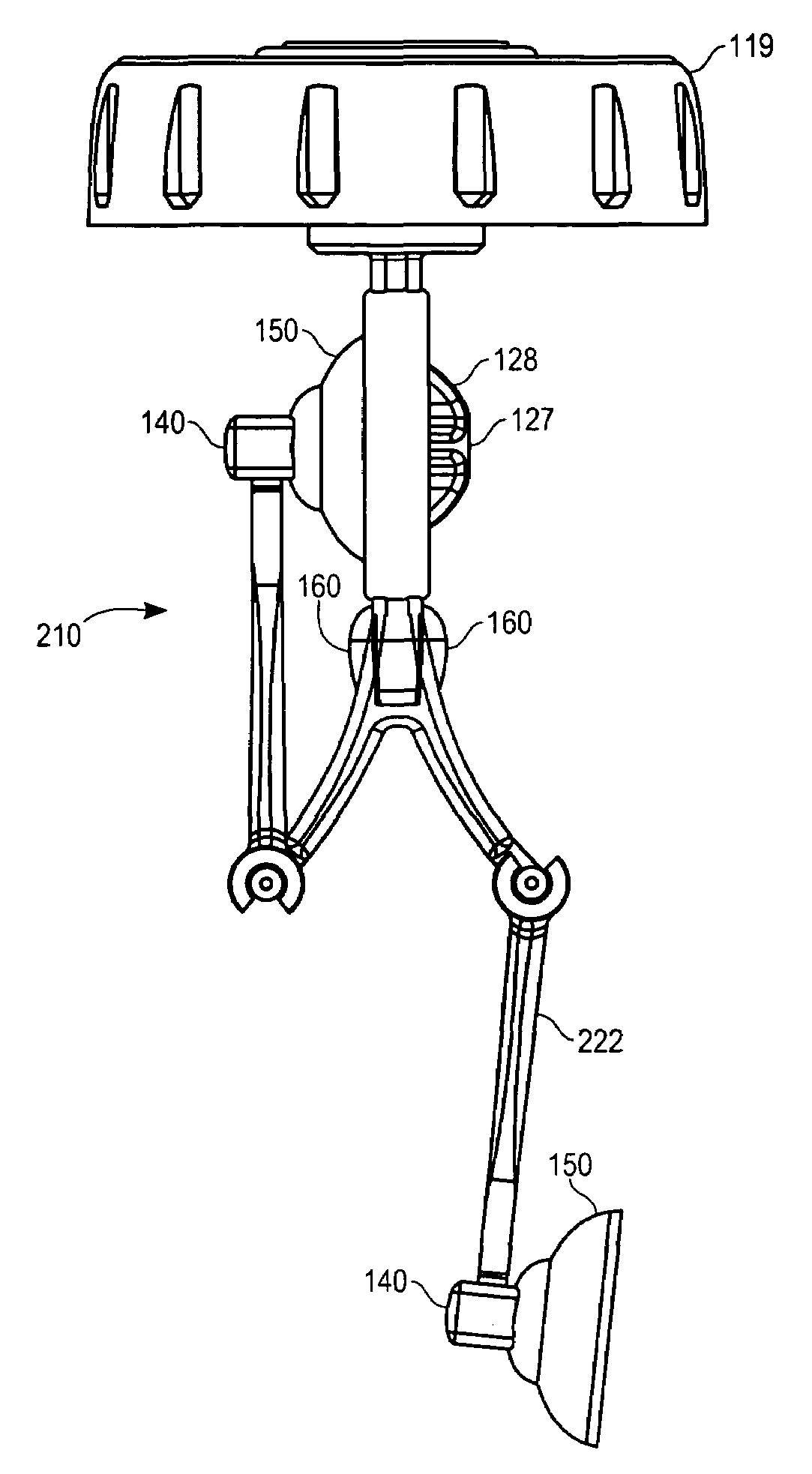
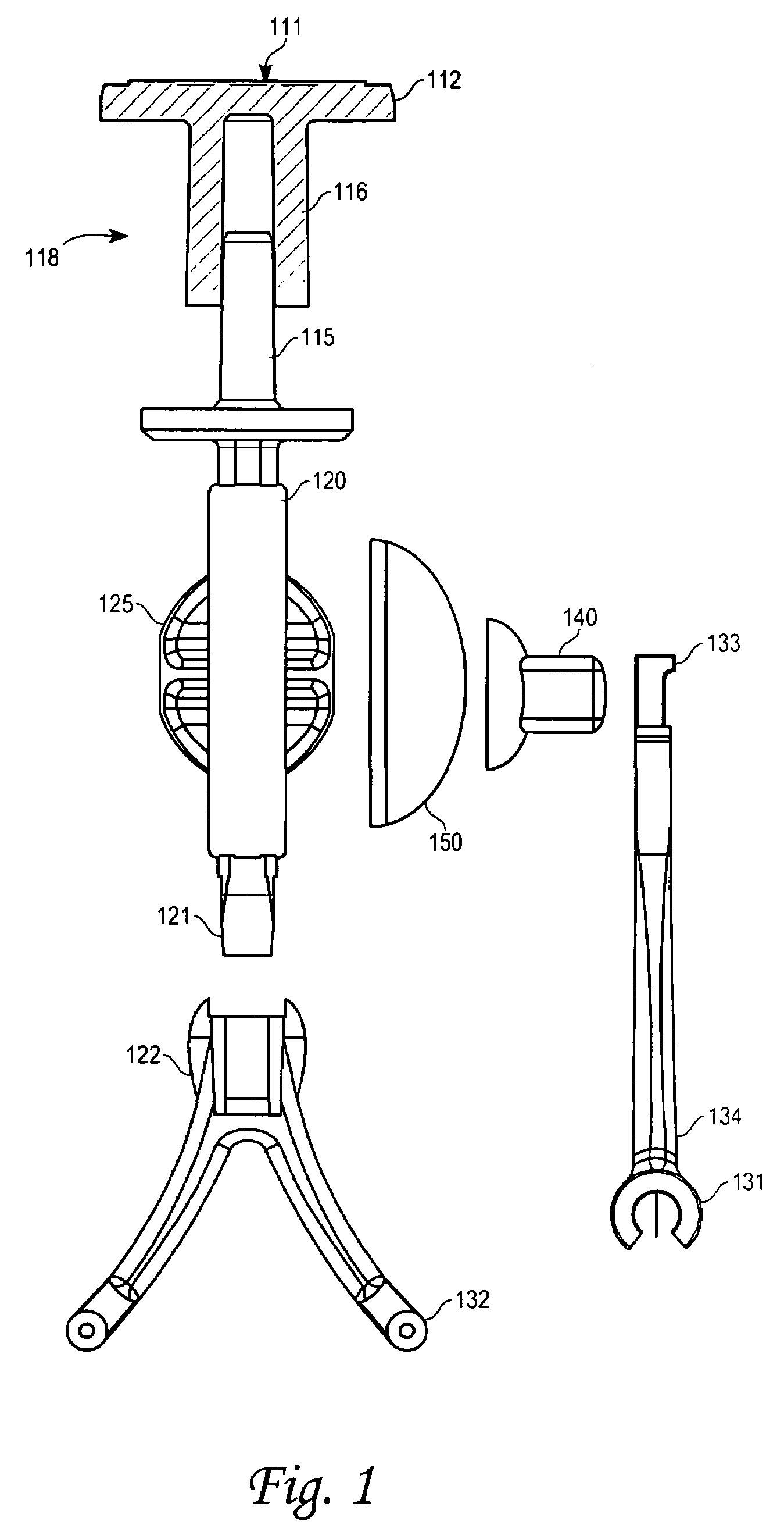
[0012]The imprint 111, FIG. 1 on the logo cap 112 can be molded in relief or otherwise printed on the top surface. The logo can be a trademark, or advertising slogan, or other commercial message modular and customizable by interchangeable selection of the logo imprint cap 112. The entire device can be assembled lacking the logo imprint cap allowing final assembly of inserting only the imprint cap.

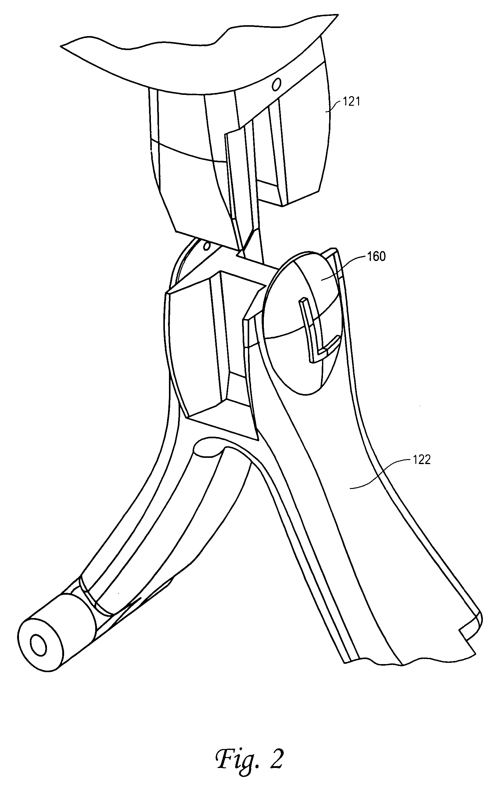
[0013]A locking outside spool 116 fits over a locking inside spool 115. The locking inside spool can be mounted to the logo imprint cap 112 and the locking outer spool 116 attached to the holder assembly 120. The inside and outside spool form a spool means 118. Between the logo imprinted cap and the holder assembly upper 120, the cap 119 not shown on FIG. 1 is sandwiched between as seen in FIG. 3, and FIG. 4. The cap 119 has a bore defining an opening such that the opening allows the cap 119 to rotate around the spool means 118. The turning of the cap 119 threaded upon the vial 510 does not...


PUM


Abstract

A contact lens case includes a cup adapted to receive minimized quantity of cleaning solution and a cap removable of the opening mouth of the cup. The lens support structure is pivotally connected to the cap that holds one of a pair of lens within the cup. The lens support structure consists of a base plate where a pair of contact lenses lay on each side and is held by a pair of swiveling arms, one on each side. The lens support structure also acts as two contact lens eye wearing device, one on each side, when removed from cup and having the arms swiveled mechanically downward. When swiveled back to upright position the suction cup at the end of the swivel holds the contact lens against the lens support structure plate.

Description

DISCUSSION OF RELATED ART[0001]Contact lenses have become popular since their inception over a decade ago. No longer are nearsighted users bound to glasses and spectacles, but users may now scuba dive, play basketball and handle a wide variety of competitive sporting events without the traditional restraint of glasses. Recently, contact lenses have become less expensive and more affordable increasing its popularity.[0002]One drawback of contact lenses is its susceptibility to protein deposits. Naturally occurring protein deposits in the eye built up over time and require a user to remove the contact lenses usually at night for storage in contact lens solution. The contact lenses are typically stored in a contact lens case. The traditional contact lens case includes a pair of containers forming shallow depressions each having a cap. A user typically stores a single contact lens in each shallow depression.[0003]While it is easy for most users to remove contact lenses, it is much more ...

Claims


Application Information

Patent Timeline
Patent Type & Authority Patents(United States)
IPC IPC(8): A61F9/00A45C11/00A45C11/04
CPCA45C11/005Y10S206/804
Inventor HUANG, JOEY
Owner HUANG JOEY
Learn More