Surgical device

a surgical device and a technology for surgical instruments, applied in the field of surgical instruments, can solve the problems of difficult placement of sealing members and plugs, serious health risks to patients, and patients' health hazards, and achieve the effects of improving patient comfort and safety, and reducing the risk of surgical complications

Inactive Publication Date: 2007-02-20
ST JUDE MEDICAL +2
View PDF6 Cites 77 Cited by
  • Summary
  • Abstract
  • Description
  • Claims
  • Application Information

AI Technical Summary

Benefits of technology

The present invention is related to a device that can hold a needle cartridge. The device includes a biasing element that can move the cartridge between two positions. The needle cartridge may have more than two slots, each containing a needle. The technical effect of this invention is to provide a device that can securely hold a needle cartridge and easily move it between two positions.

Problems solved by technology

The technical problem addressed in this patent is the need for a more efficient and safe method for sealing punctures in blood vessels and other anatomical structures, as current methods require the use of needles which are difficult to handle and may pose health risks to the patient.

Method used


Image

  • Surgical device
  • Surgical device
  • Surgical device

Examples


Embodiment Construction

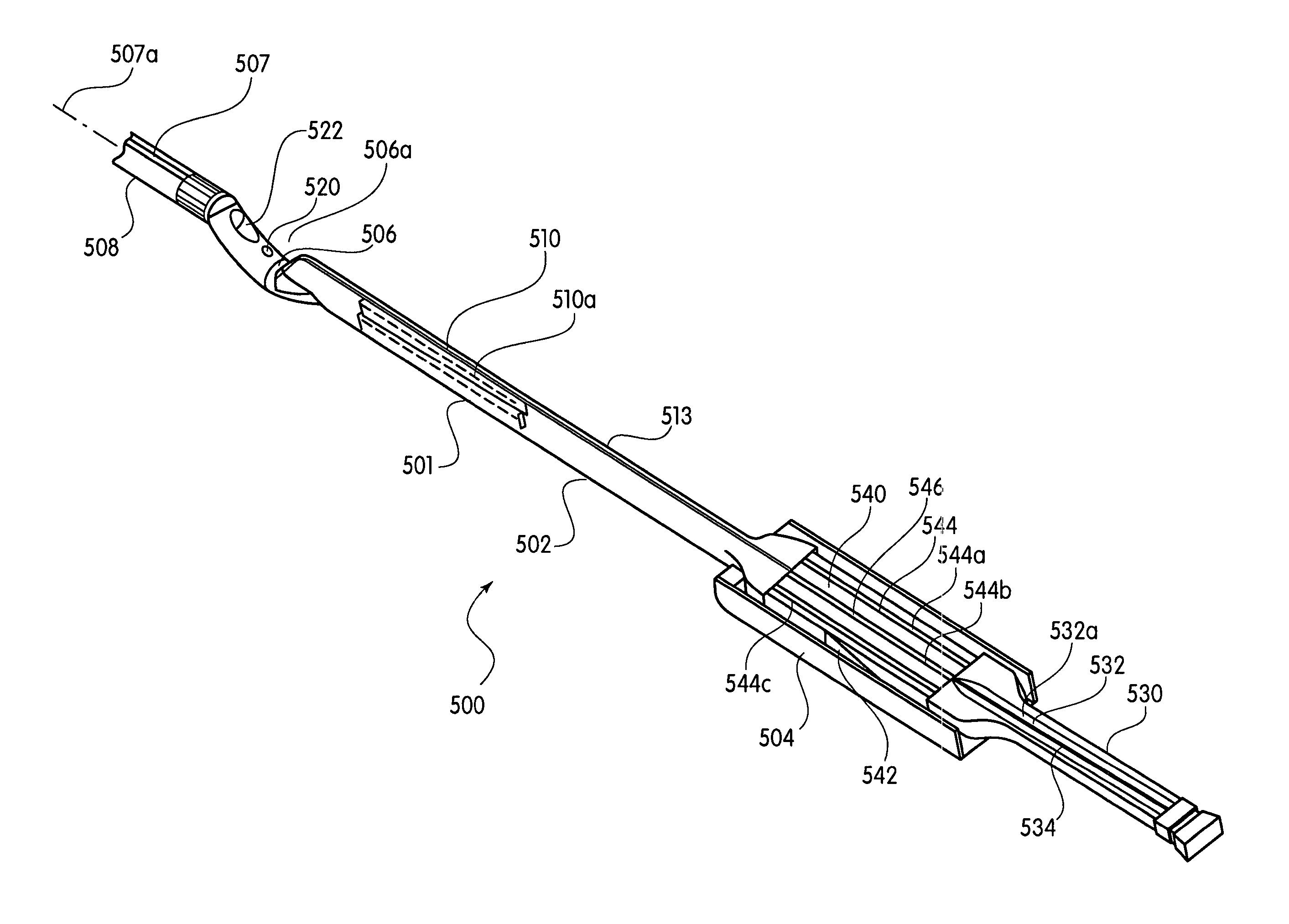
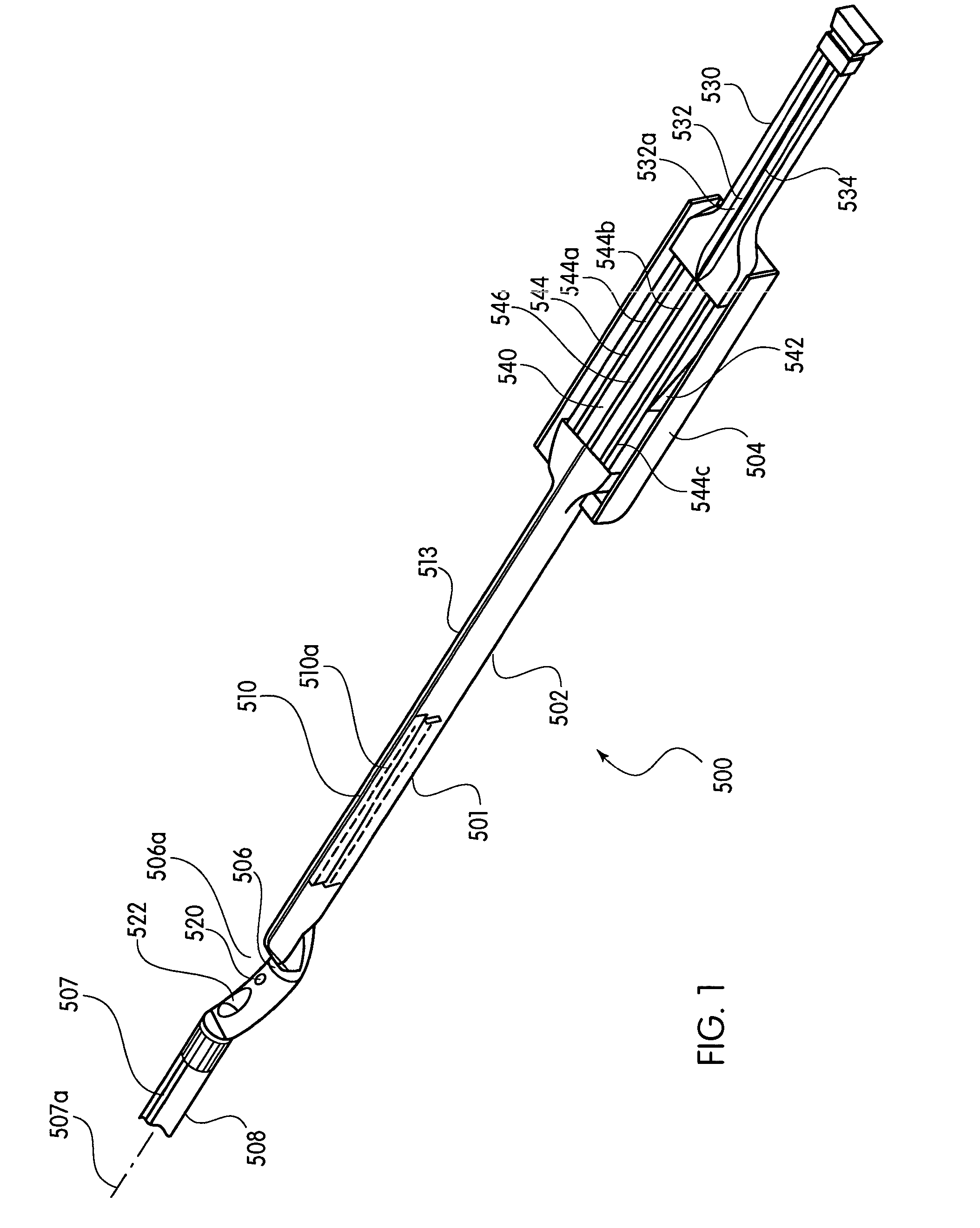
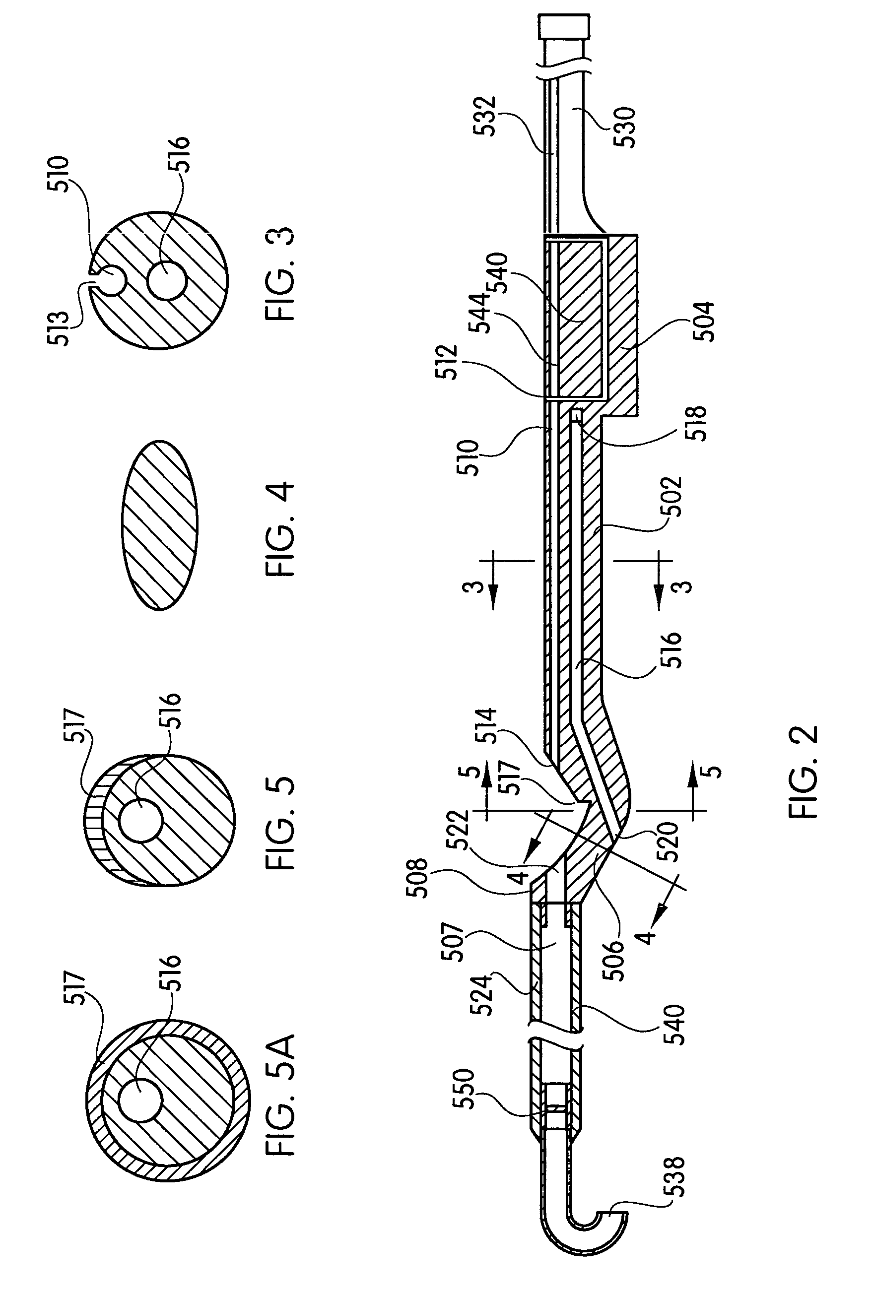
[0025]FIG. 1 shows a suture device 500 according to one embodiment of the present invention. The suture device 500 includes a tube 501 having a substantially circular cross-section. The suture device 500 includes a distal part 508 that defines a distal lumen 507 having a central axis 507a, a proximal part 502 that defines a needle insertion lumen 510 having a central axis 510a, and a housing 504 attached to a proximal end of the proximal part 502. A suture removal slot 513 extends along the surface of the proximal part 502 and communicates with the needle insertion lumen 510 so as to open an interior of the needle insertion lumen 510 to the outside of the device 500 along an entire length of the needle insertion lumen 510. As shown in FIG. 3, a width of the suture removal slot 513 is less than a diameter of a needle inserted through the needle insertion lumen 510 so that a needle received in the needle insertion lumen 510 can not escape from the needle insertion lumen 510 via the su...


PUM


Abstract

A device for automatically providing needles to a sealing apparatus for sealing a puncture in an anatomical structure, the sealing apparatus including a needle insertion lumen and a needle pusher channel having a needle pusher disposed therein. The device may include a housing coupled to the sealing apparatus and a cartridge disposed in the housing. The cartridge has a first and a second needle slot extending from a distal end of the cartridge to a proximal end of the cartridge. The first and second needle slots have first and second needles disposed, e.g., pre-loaded, therein, respectively. The cartridge is moveable, such as by a biasing element, relative to the housing between a first position in which the first needle slot is aligned with the needle insertion lumen and the needle pushing channel, and a second position in which the second needle slot is aligned with the needle insertion lumen and the needle pushing channel.

Description


Claims


Application Information

Patent Timeline
Owner ST JUDE MEDICAL
Why Eureka
Try Eureka