Distal end cutter

a cutter and distal end technology, applied in the field of dental instruments, can solve the problems of not being held with the desired level of certainty, known cutters have limitations, and wire can be cu

Inactive Publication Date: 2007-02-27
HU FRIEDY MFG
View PDF14 Cites 13 Cited by
  • Summary
  • Abstract
  • Description
  • Claims
  • Application Information

AI Technical Summary

Problems solved by technology

The known cutter however has limitations.
When the wire length, that extends from the distal end of the bracket, dimensionally falls between the width of the cutting blades and the contact point of the O-ring, the wire can be cut, but may not be held with a desired level of certainty.

Method used


Image

  • Distal end cutter
  • Distal end cutter
  • Distal end cutter

Examples


Embodiment Construction

[0023]While embodiments of this invention can take many different forms, specific embodiments thereof are shown in the drawings and will be described herein in detail with the understanding that the present disclosure is to be considered as an exemplification of the principles of the invention and is not intended to limit the invention to the specific embodiment illustrated.

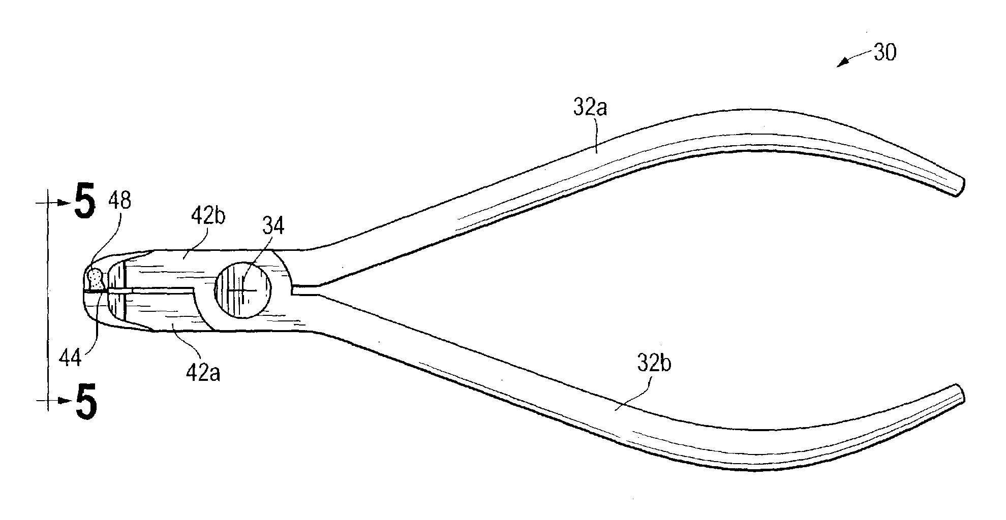
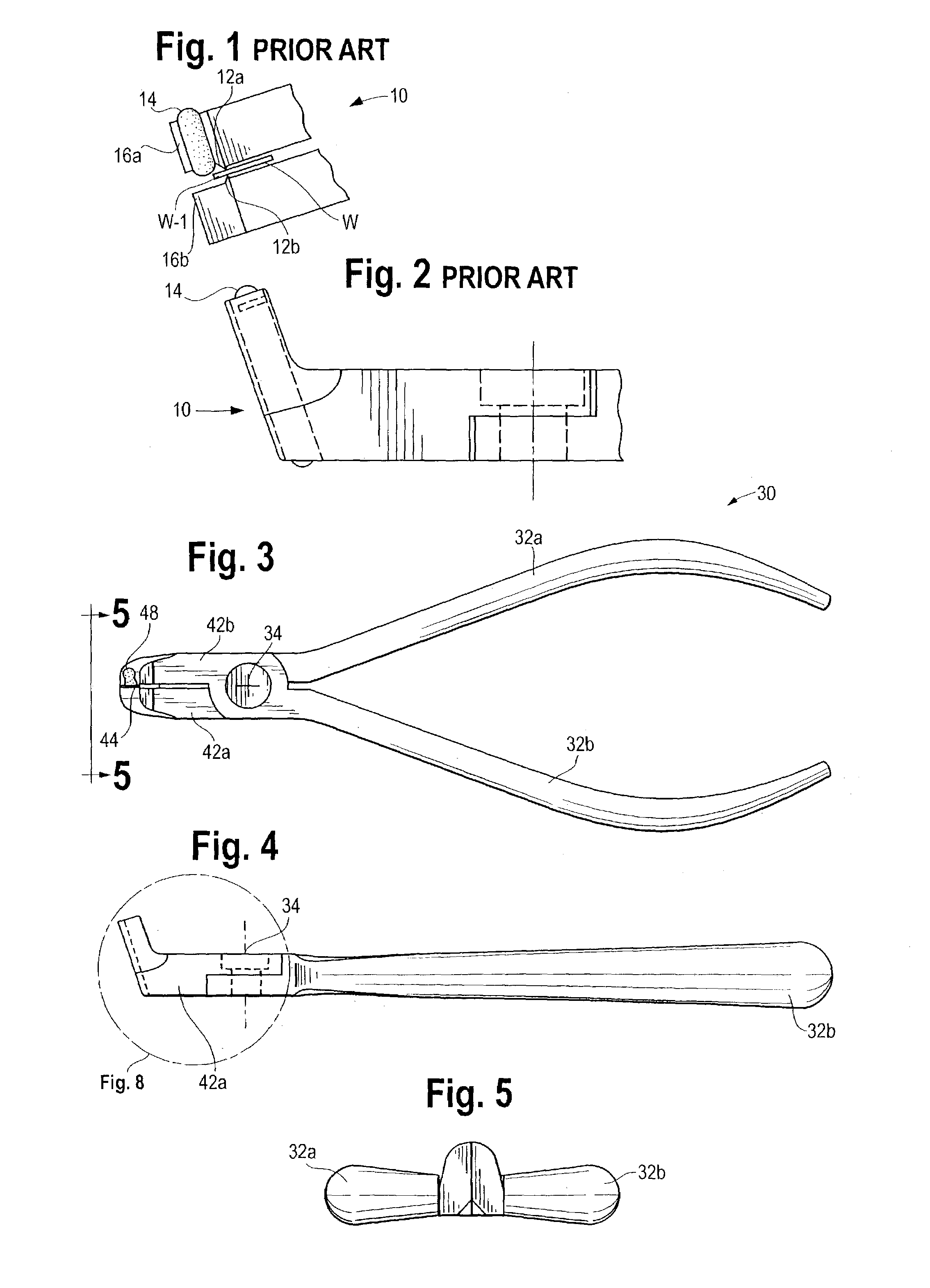
[0024]A flush cut and hold orthodontic cutter cuts orthodontic wire. When it cuts these wires, the cut portion of the wire is held within the jaws of the cutter.

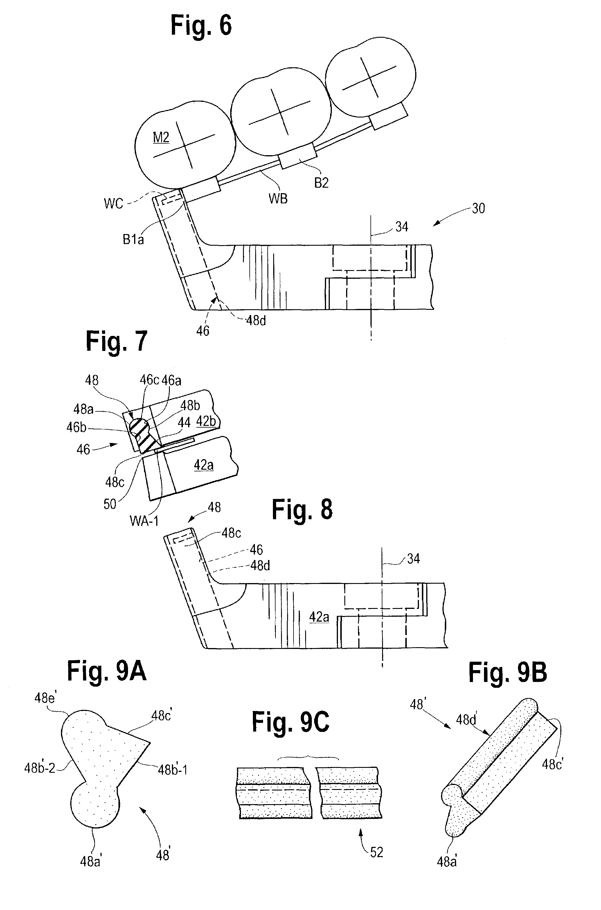
[0025]The subject cutter incorporates an elastomeric, for example silicone, deformable element installed in one side of the cutter's blades. This element acts as a wire clamping device that allows the cutter's blades to be in contact with the distal surface of an orthodontic bracket during the cutting operation.

[0026]The elastomeric element is soft and pliable so that it can receive and clamp a full range of orthodontic wires reliably. The clamping portio...


PUM


Abstract

A flush cutter of wires located on a patient's teeth has at least one pivotably carried cutting edge. An outer surface of the edge can be positioned adjacent to a surface from which the wire protrudes. An elastic insert or clamp, for griping cut wire ends, is carried adjacent to the edge. The insert has first and second spaced apart ends. A rigid surface is located to pivot toward the edge. The elastic clamp extends, in part, to the inner surface of the edge. As the cutting edge moves toward the rigid surface to cut the wire, the elastic clamp grips the cutoff wire end for removal. The rigid surface can be formed as a second cutting edge that moves toward the one cutting edge.

Description

[0001]The benefit of a Jan. 4, 2002 filing date for Provisional Patent Application Ser. No. 60 / 345,387 is hereby claimed.FIELD OF THE INVENTION[0002]The invention pertains to dental instruments. More particularly, the invention pertains to wire cutters usable by orthodontists.BACKGROUND OF THE INVENTION[0003]In the process of adjusting location or spacing of teeth for a patient, an orthodontist will attach brackets to the respective teeth. One or more wires can be installed between brackets to enable the orthodontist to move one or more selected teeth with forces applied via the wire or wires. The ends of the wires, extending from brackets, need to be trimmed flush with the adjacent bracket(s) for patient comfort. The cut wire ends are then removed from the patient's mouth.[0004]A known cutter employs a rubber O-ring for the purpose of gripping cut off pieces of wire. The known cutter however has limitations. When the wire length, that extends from the distal end of the bracket, dim...

Claims


Application Information

Patent Timeline
Patent Type & Authority Patents(United States)
IPC IPC(8): A61C3/00B25F3/00A61C7/04
CPCA61C7/04
Inventor SMITH, LARRY E.GURCZAK, ANDYSEERALAN, RAVI P.SCHINDLER, RONALD J.
Owner HU FRIEDY MFG
Why Eureka
Try Eureka