Process for fabrication of a ferrocapacitor

a technology of ferrocapacitors and fabrication processes, which is applied in the direction of capacitors, semiconductor devices, electrical devices, etc., can solve problems such as interference with device operation, and achieve the effect of improving the performance and consistency of ferrocapacitors

Inactive Publication Date: 2007-02-27
QIMONDA
View PDF8 Cites 0 Cited by
  • Summary
  • Abstract
  • Description
  • Claims
  • Application Information

AI Technical Summary

Benefits of technology

[0011]Thus, the crystallisation of the PZT proceeds from the side walls. Thus, the crystal boundaries in the PZT tend to be horizontal, i.e parallel to the electric field direction in the device, thus improving the performance and consistency of the ferrocapacitors.

Problems solved by technology

The present inventors have realized that the crystallisation step of the conventional method described above has the disadvantage that crystal boundaries in the PZT (which are generally parallel to the crystallisation direction) tend to be vertical, which also implies that they are orthogonal to the electric field direction when the ferrocapacitors are in use.
Therefore the grain boundaries, which intercept all the electric field lines, may interfere with the operation of the device.

Method used


Image

  • Process for fabrication of a ferrocapacitor
  • Process for fabrication of a ferrocapacitor

Examples


Embodiment Construction

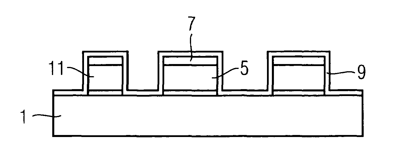
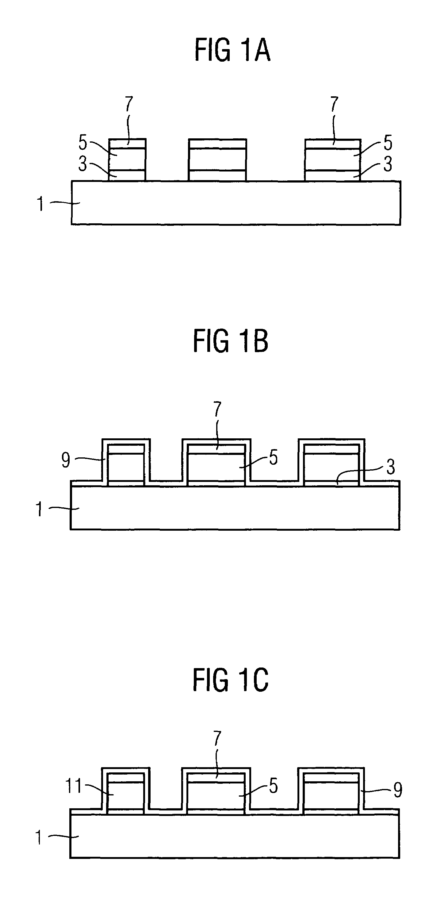
[0029]Referring firstly to FIG. 1(a), a structure is shown which is formed during a ferroelectric capacitor fabrication process which is an embodiment of the invention. A substrate 1 is shown which may be TEOS. This substrate may correspond exactly to the substructure of conventional devices discussed above. Below the substrate 1 may be located electronic components, and electrically conductive plugs (not shown) may extend upward through the substrate 1, e.g. terminating at in TiN / Ir barrier elements.

[0030]On the TEOS layer 1 are elements 3 of a chemically inert and electrically insulating bottom isolation layer (e.g. Al2O3 or Ta2O5). Over the elements 3 are ferroelectric elements 5 of PZT and further elements 7 of the same chemically inert material which forms layer 3. The PZT elements 5 and elements 3, 7 were formed from respective layers of amorphous PZT and the non-conductive matter (e.g. Al2O3) which were formed over the TEOS layer 1 (e.g. by sputtering, at least in the case of...


PUM

PropertyMeasurementUnit
temperatureaaaaaaaaaa
ferroelectricaaaaaaaaaa
electrically insulatingaaaaaaaaaa

Abstract

A process for fabricating a ferrocapacitor comprises etching a layer of amorphous PZT formed over a layer having a low concentration of nucleation centres for PZT crystallisatlon. The etching step forms individual PZT elements. The side surfaces of the PZT elements are then coated with a layer of a material which promotes crystallisation of the PZT, such as one having a high concentration of PZT crystallisation centres (e.g. TiO2), and a PZT annealing step is carried out. The result is that the PZT has a high degree of crystallisation, with grain boundaries extending substantially horizontally through the PZT elements.

Description

FIELD OF THE INVENTION[0001]The present invention relates to fabrication processes for ferroelectric devices which include one or more ferrocapacitors, and to ferroelectric devices produced by the fabrication processes.BACKGROUND OF INVENTION[0002]Many conventional FeRAM devices include a horizontal ferrocapacitor structure, in which a stack of layers is formed including top and bottom electrodes sandwiching a ferroelectric layer. An alternative “vertical capacitor” structure was suggested in U.S. Pat. No. 6,300,652, the disclosure of which is incorporated herein by reference. A vertical capacitor includes a ferroelectric element sandwiched between electrodes to either side, all at substantially the same level in the FeRAM device.[0003]The vertical capacitors are typically to be formed over a substructure. The substructure includes various electronic components buried in a matrix (e.g. of TEOS (tetraethylorthosilicate)). The substructure further includes conductive plugs connected t...

Claims


Application Information

Patent Timeline
Patent Type & Authority Patents(United States)
IPC IPC(8): H01L21/00H01L21/02H01L21/314H01L21/316
CPCH01L21/02197H01L28/56H01L21/31691
Inventor BRUCHHAUS, RAINERHORNIK, KARL
Owner QIMONDA
Why Eureka
Try Eureka