Container adapted to hold and dispense bagged fluids

a technology for containers and fluids, applied in the direction of pliable tubular containers, liquid handling, instruments, etc., can solve the problems of not always the best choice, wasteful storage vessels, and not always sanitary storage, etc., and achieve the effect of convenient storage and us

Inactive Publication Date: 2007-03-13
INT PACKAGING INNOVATIONS
View PDF76 Cites 54 Cited by
  • Summary
  • Abstract
  • Description
  • Claims
  • Application Information

AI Technical Summary

Problems solved by technology

While this is a universally used design, it is not always the best choice from a storage point of view.
The design of most storage vessels is often wasteful when placed in a refrigerator and also does not always provide for as sanitary storage as would be desired.
This storage space is often limited to a single shelf of the refrigerator (often the top shelf) which can make storing the jugs and using the jugs difficult.
Further, to be able to pour from these vessels, they often have handles which stick outwards from them and increase the effective footprint of the vessel, therefore requiring more shelf space than is desirable.
Liquid dispensers, however, have the problem of being damaged by fluids within them.
In this arrangement, the inside surfaces of the dispenser can become contaminated with particles of the fluid or items suspended in the fluid.
Further, taste and odors from the soft drink mix can permeate the vessel.
This “contamination” can cause problems to the vessel.
For one, contamination can change the taste of other fluids dispensed from the vessel in an unpleasant fashion.
For instance, a grape flavoring contaminating a vessel can be partially transferred to later added ice tea flavoring, creating an unpleasant combination.
Sometimes, a strongly flavored beverage can so impregnate the walls that its scent or taste cannot be removed even with a thorough cleaning.
This can prevent a vessel from being reused with other flavors of fluid, and can even require the vessel's destruction if it cannot be used anymore due to the flavor impregnation.
Contamination can also lead to the introduction or growth of microorganisms which can make the vessel unsanitary for future use regardless of the impact on flavor.
Further, because the vessel must be “watertight” in order to prevent leakage of the fluid being dispensed, market distribution and storage of empty dispensers, or dispensers sold with fluid therein, will often take up significant space inefficiently, as such dispensers often cannot collapse and are not sized and shaped to pack efficiently for travel.
Therefore, a user may often have wasted space taken up by the dispenser when it is not in use because the dispenser cannot be broken down or collapsed.
Further, because it is generally a fairly costly device, users are reluctant to discard an unused dispenser unless they are certain they have no further need for it.

Method used


Image

  • Container adapted to hold and dispense bagged fluids
  • Container adapted to hold and dispense bagged fluids
  • Container adapted to hold and dispense bagged fluids

Examples


first embodiment

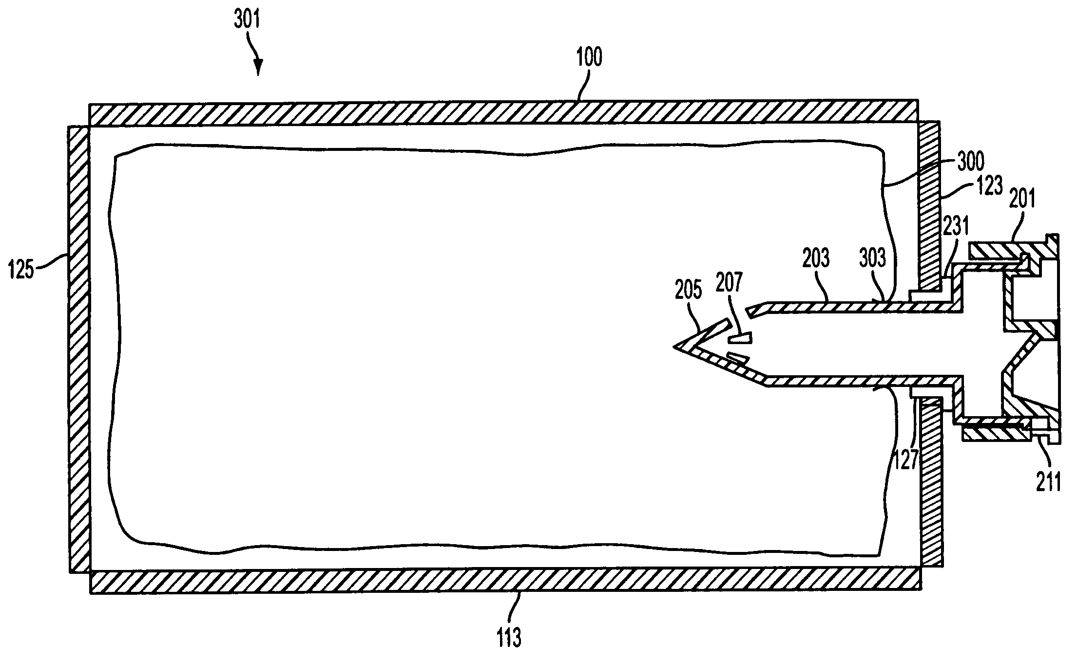
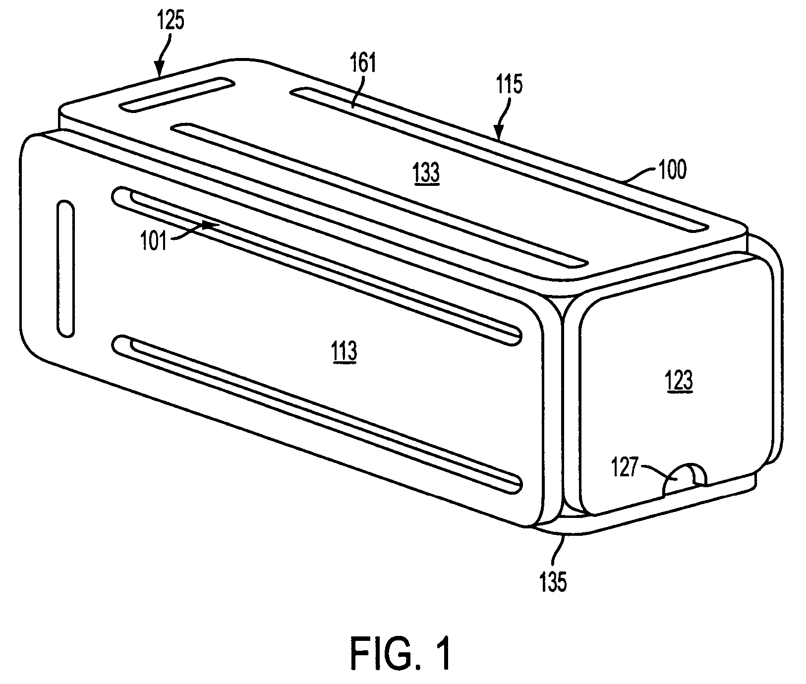
[0041]The container embodiments shown in FIGS. 1, 4, and 7 are designed to be used in combination with a bag of fluid so as to provide a fluid dispensing apparatus. The following description of the use of a bag (300) of fluid with the an embodiment of the container (100, 150, or 700) will reference primarily the container (100) but is generally applicable to other embodiments. In an embodiment of the dispensing apparatus a bag (300) of fluid is positioned in the internal volume (101) of a container (100) and enclosed thereby. The bag (300) positioned in a container (100) may be adhered to the container (100) for any reason such as providing added support and stability to the bag (300) but is preferably not so adhered to the container (100). A user then inserts a spike (201) through the aperture (127) in the container (100) and through the outer wall of the bag (300), both connecting the spike (201) with the container (100) and puncturing the bag (300) in essentially the same motion....

third embodiment

[0046]In an alternative embodiment, such as one using the container (700), wherein the spike (201) projects upwardly (as shown in FIG. 7), the weight of the of the fluid in the bag (300) is used to push the outer wall of the bag (300) onto the spike (201) that is already attached to the container (700). In such an embodiment, the combined weight of the bag (300) and the fluid in the bag (300) supplies sufficient force that the spike (201) penetrates the outer wall of the bag (300), connecting the spike (201) directly to the fluid inside the bag (300).

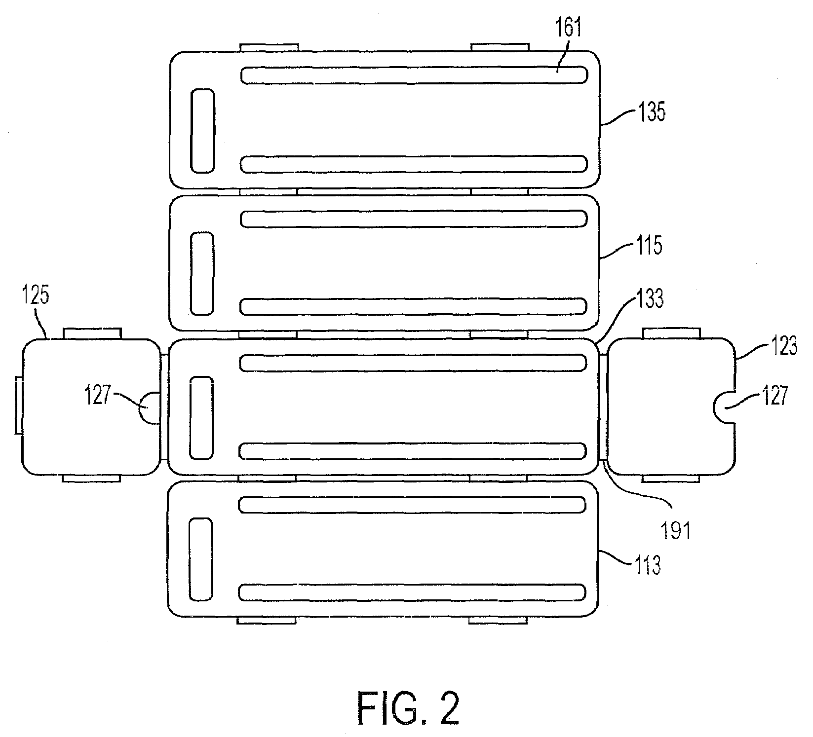
[0047]In an alternate embodiment using the first embodiment of the container (100) the end (123) is attached to another panel of the container (100) at a hinge that includes a spring or similar biasing device (191) that tends to rotate the end (123) from a flat position as in FIG. 2 into an uprights position as in FIG. 1. With this embodiment, the user can place the bag (300) in the container (100), mount the spike (201) in the aperture...


PUM


Abstract

A fluid dispensing apparatus comprising a bag containing fluid, a container that provides support for the bag, a spike comprising a hollow stem through which fluid can flow, the spike being connected to the bag at a joint created upon the puncturing of the bag by the spike, and a dispensing mechanism for controlling the flow of fluid from the bag, which dispensing mechanism is connected to the hollow stem, and wherein the dispensing mechanism is operated to allow fluid flow.

Description

CROSS REFERENCE TO RELATED APPLICATIONS[0001]This application claims the benefit of U.S. Provisional Patent Applications No. 60 / 513,769, filed Oct. 23, 2003, and 60 / 545,155, filed Feb. 17, 2004, the entire disclosures of which are herein incorporated by reference.BACKGROUND OF THE INVENTION[0002]1. Field of Invention[0003]The invention relates generally to a dispensing apparatus for bagged fluids.[0004]2. Description of Related Art[0005]Liquid storage vessels such as jugs or pitchers are essentially ubiquitous in society and have been around in a general form for centuries. A liquid storage vessel generally serves two purposes. It serves to contain a liquid so that the liquid does not spill, evaporate, or be soaked up by other objects from which it cannot easily be removed, and it serves as a way to dispense the liquid to users to drink, wash with, or otherwise utilize.[0006]As technology has improved, the jug has become lighter, easier to use and store, and easier to handle and dis...

Claims


Application Information

Patent Timeline
Patent Type & Authority Patents(United States)
IPC IPC(8): B65D35/28B65D35/56B65D77/06B67B7/86B67D3/00B67D3/04B67D99/00
CPCB65D11/18B65D11/1806B65D11/1873B65D77/06B67D3/04B67B7/28B67D3/0019B67D3/0029B65D77/068
Inventor MILLER, DONMACLER, II, HENRY H.MACLER, JEFFREY E.AVERY, STEVEN
Owner INT PACKAGING INNOVATIONS
Why Eureka
Try Eureka