Support device destined to be anchored in the ground

a technology of supporting devices and ground, applied in the direction of machine supports, domestic objects, applications, etc., can solve the problems of difficult removal of soil therefrom, and achieve the effect of preventing free flow

Inactive Publication Date: 2007-03-20
PATSALARIDIS DIMITRIOS
View PDF25 Cites 25 Cited by
  • Summary
  • Abstract
  • Description
  • Claims
  • Application Information

AI Technical Summary

Problems solved by technology

However, when soil engages and packs itself into the tubular body of the post, it may be difficult to remove this soil therefrom.

Method used


Image

  • Support device destined to be anchored in the ground
  • Support device destined to be anchored in the ground
  • Support device destined to be anchored in the ground

Examples


Embodiment Construction

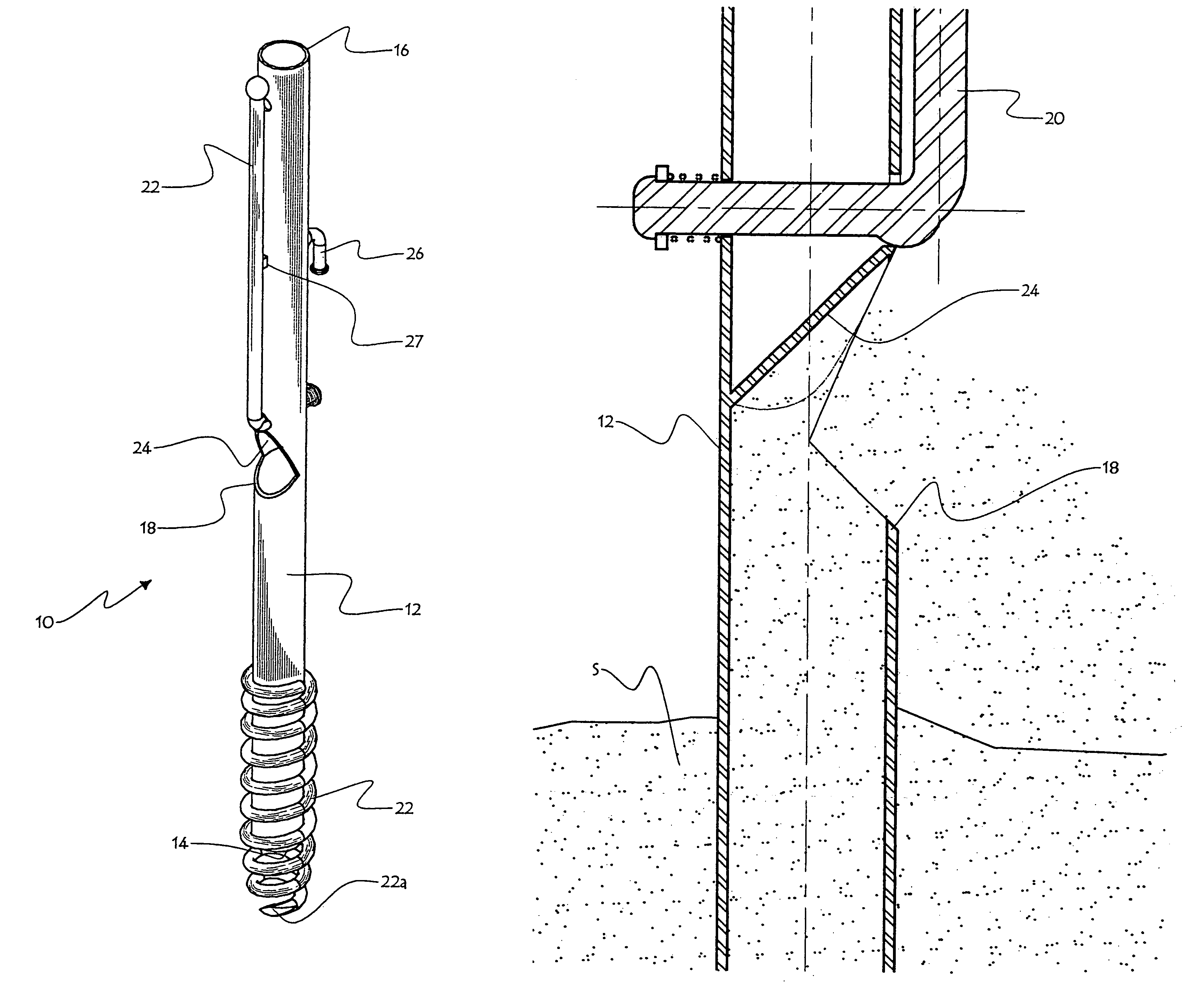
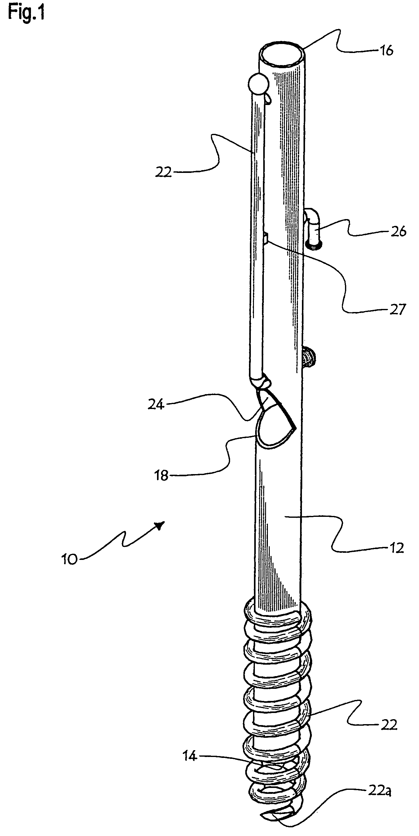
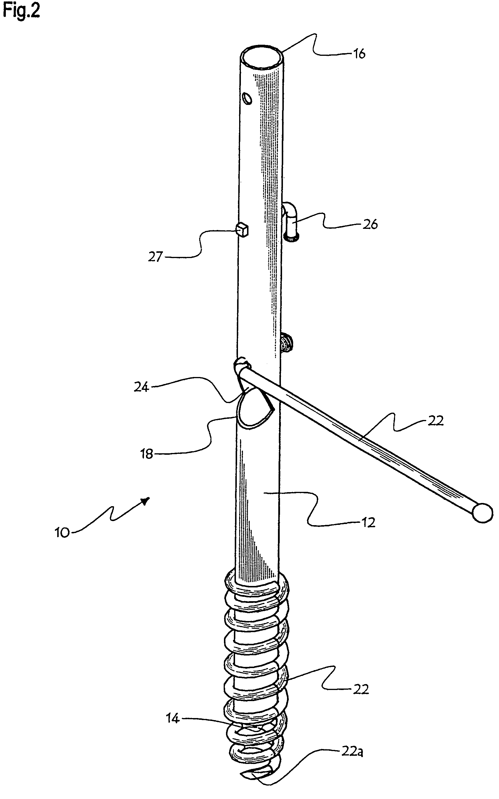
[0033]FIGS. 1 to 4 show the support device 10 of the invention, for use on a ground S of granular material, and for use in supporting an object not part of the invention, for example a sunshade, fixedly over ground.

[0034]The support device 10 comprises a hollow tubular section post 12 defining two ends: a lower end corresponding to the end which may be anchored into ground S, and an upper end, opposite the lower end.

[0035]A lower aperture 14 is formed at the lower end of the post 12. An upper aperture 16 is formed at the upper end of the post 12.

[0036]A pointed-tip helix-shaped bar 22 is fixedly attached to the lower portion of the post 12, as shown in FIG. 1. This helix-shaped bar 22 represents a screw means for the device 10. The helix-shaped bar 22 is for use in assisting the user of device 10 to anchor device 10 into ground S. The purpose of helix-shaped bar 22 is similar to that of the threads of a screw. A lower converging portion 22a of helix-shaped bar 22 extends downwardly ...


PUM


Abstract

The device, destined to be anchored in the ground of granular composition, comprises a rod with a hollow tubular section, the latter having an open upper end wherein can be fixed an object and an intermediate orifice on its flank. The orifice enables evacuation of the granular matter constituting the ground and penetrating into the rod through its open lower end when the device is being anchored in the ground.

Description

FIELD OF THE INVENTION[0001]This invention generally relates to support devices and more particularly to a support device which can be anchored into the ground so as to maintain an object fixedly over ground.BACKGROUND OF THE INVENTION[0002]There are many different shapes of support devices to be anchored into the ground. A review of prior art reveals the existence of several devices which can be anchored into ground, more particularly into soil made of granular compound material, such as earth, sand, snow, or the like. To facilitate reading, we will use occasionally earth as an example of such compound. A large number of support devices exist and are different from one another mainly by the geometry of the support tip destined to be driven into ground.[0003]Among these devices, we will draw attention to support devices which comprise a tubular post with hollow section, which become upright upon being anchored into ground. The lower end of the post destined to be anchored into groun...

Claims


Application Information

Patent Timeline
Patent Type & Authority Patents(United States)
IPC IPC(8): F16M13/00E04H12/22
CPCE04H12/2223
Inventor PATSALARIDIS, DIMITRIOS
Owner PATSALARIDIS DIMITRIOS
Why Eureka
Try Eureka