Counter-rotating turbine engine and method of assembling same

a technology of counter-rotating and low-pressure turbines, which is applied in the direction of machines/engines, liquid fuel engines, sliding contact bearings, etc., can solve the problems of negating the benefits of utilizing a counter-rotating low-pressure turbine, and achieve the effect of facilitating the improvement of clearance control

Active Publication Date: 2007-03-27
GENERAL ELECTRIC CO
View PDF21 Cites 67 Cited by
  • Summary
  • Abstract
  • Description
  • Claims
  • Application Information

AI Technical Summary

Benefits of technology

[0006]In one aspect, a method for assembling a gas turbine engine is provided. The method includes providing a low-pressure turbine inner rotor configured to rotate in a first direction, providing a low-pressure turbine outer rotor configured to rotate in a second direction that is opposite the first rotational direction, and coupling at least one foil bearing to at least one of the inner and outer rotors to facilitate improving clearance control between a first rotating component and at least one of a second rotating component and a non-rotating component.

Problems solved by technology

As such, during operation, the performance penalties associated with the increased weight and size may actually negate the benefits of utilizing a counter-rotating low-pressure turbine.

Method used


Image

  • Counter-rotating turbine engine and method of assembling same
  • Counter-rotating turbine engine and method of assembling same
  • Counter-rotating turbine engine and method of assembling same

Examples


Embodiment Construction

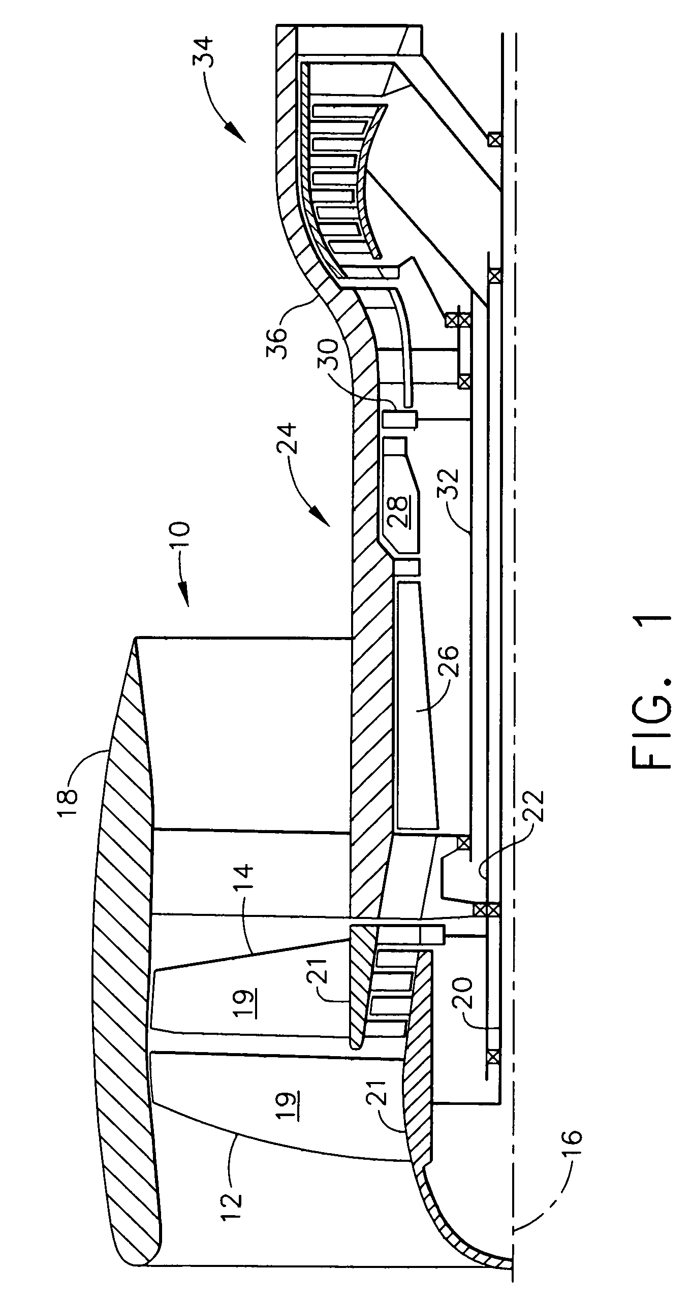
[0021]FIG. 1 is a cross-sectional view of a portion of an exemplary gas turbine engine 10 that includes a forward fan assembly 12 and an aft fan assembly 14 disposed about a longitudinal centerline axis 16. The terms “forward fan” and “aft fan” are used herein to indicate that one of the fans 12 is coupled axially upstream from the other fan 14. In one embodiment, fan assemblies 12 and 14 are positioned at a forward end of gas turbine engine 10 as illustrated. In an alternative embodiment, fan assemblies 12 and 14 are positioned at an aft end of gas turbine engine 10. Fan assemblies 12 and 14 each include a plurality of rows of fan blades 19 positioned within a nacelle 18. Blades 19 are joined to respective rotor disks 21 that are rotatably coupled through a respective fan shaft 20 to forward fan assembly 12 and through a fan shaft 22 to aft fan assembly 14.

[0022]Gas turbine engine 10 also includes a core engine 24 that is downstream from fan assemblies 12 and 14. Core engine 24 inc...


PUM


Abstract

A method for assembling a gas turbine engine that includes providing a low-pressure turbine inner rotor configured to rotate in a first direction, providing a low-pressure turbine outer rotor configured to rotate in a second direction that is opposite the first rotational direction, and coupling at least one foil bearing to at least one of the inner and outer rotors to facilitate improving clearance control between a first rotating component and at least one of a second rotating component and a non-rotating component.

Description

STATEMENT REGARDING FEDERALLY SPONSORED RESEARCH & DEVELOPMENT[0001]The U.S. Government may have certain rights in this invention pursuant to Take Order NAS2-01135 Task Order #2.BACKGROUND OF THE INVENTION[0002]This invention relates generally to aircraft gas turbine engines, and more specifically to counter-rotating gas turbine engines.[0003]At least one known gas turbine engine includes, in serial flow arrangement, a forward fan assembly, an aft fan assembly, a high-pressure compressor for compressing air flowing through the engine, a combustor for mixing fuel with the compressed air such that the mixture may be ignited, and a high-pressure turbine. The high-pressure compressor, combustor and high-pressure turbine are sometimes collectively referred to as the core engine. In operation, the core engine generates combustion gases which are discharged downstream to a counter-rotating low-pressure turbine that extracts energy therefrom for powering the forward and aft fan assemblies. ...

Claims


Application Information

Patent Timeline
Patent Type & Authority Patents(United States)
IPC IPC(8): F01D1/24
CPCF01D1/24F01D25/16F02C3/067F16C17/18F16C17/024F02K3/072F05D2240/53F16C2360/23
Inventor SEDA, JORGE FRANCISCOMONIZ, THOMAS ORYBUTLER, LAWRENCE
Owner GENERAL ELECTRIC CO
Why Eureka
Try Eureka