Apparatus and methods for illuminating optical systems

a technology of illumination and optical systems, applied in the field of illumination devices and methods, can solve the problems of increasing the cost of many applications, affecting the efficiency of illumination, and affecting the efficiency of illumination, and achieve the effect of balancing optical power

Active Publication Date: 2007-03-27
SYNOPSYS INC
View PDF57 Cites 29 Cited by
  • Summary
  • Abstract
  • Description
  • Claims
  • Application Information

AI Technical Summary

Benefits of technology

[0010]Another embodiment of the invention comprises a method of manufacturing a head mounted display, said method comprising: disposing an optical conveyance with respect to a light source to receive light therefrom, said optical conveyance having first and second sections; disposing distal ends of said first and second sections of said optical conveyance to direct light output from said distal ends to respective first and second reflective surfaces; orienting said first and second reflective surfaces to aim light output from said first and second sections of said optical conveyance toward respective first and second regions of a spatial light modulator, said first and second sections of said optical conveyance providing substantially balanced optical power to said first and second regions of said spatial light modulator; and disposing imaging optics with respect to said spatial light modulator to receive light from said first and second regions of said spatial light modulator and to project said light for forming of images of said first and second regions.

Problems solved by technology

As many components are included in the optical systems, the products become larger, heavier, and more expensive than desired for many applications.

Method used


Image

  • Apparatus and methods for illuminating optical systems
  • Apparatus and methods for illuminating optical systems
  • Apparatus and methods for illuminating optical systems

Examples


Embodiment Construction

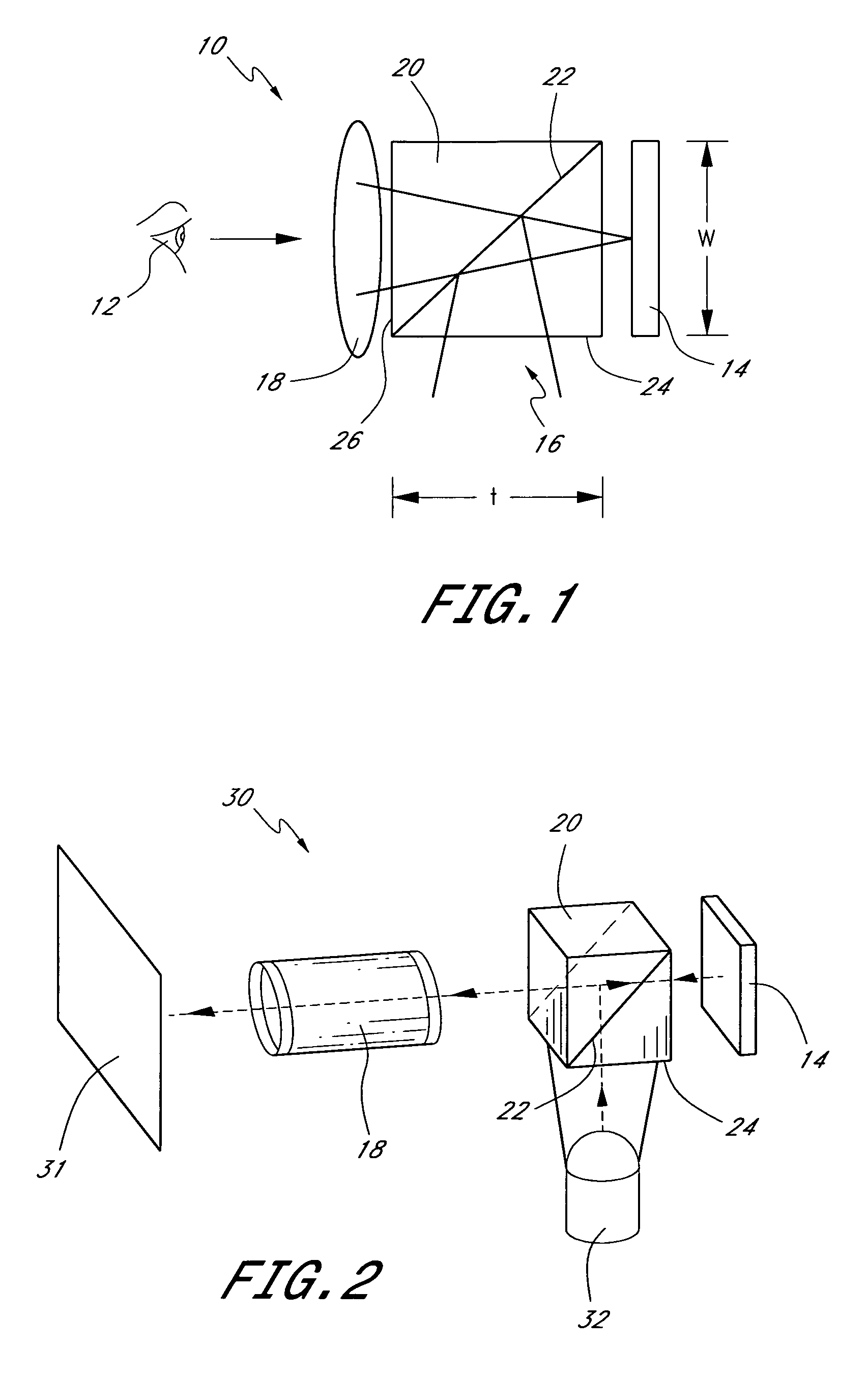
[0061]To present graphics or other visual information to a viewer, images and / or symbols, e.g., text or numbers, can be projected onto a screen or directed into the viewer's eye. FIG. 1 schematically illustrates a display 10 disposed in front of a viewer 12 (represented by an eye). In a preferred embodiment, this display 10 includes a spatial light modulator 14 that is illuminated with light 16 and imaged with imaging or projection optics 18. The spatial light modulator 14 may comprise, for example, a reflective polarization modulator such as a reflective liquid crystal display. This liquid crystal spatial light modulator preferably comprises an array of liquid crystal cells each which can be individually activated by signals, e.g., analog or digital, to produce a high resolution pattern including characters and / or images. More generally, the spatial light modulator may comprise an array of modulators or pixels that can be selectively adjusted to modulate light. The projection optic...


PUM


Abstract

Various embodiments involving structures and methods for illumination can be employed, for example, in projectors, head-mounted displays, helmet-mounted displays, back projection TVs, flat panel displays as well as other optical systems. Certain embodiments may include prism elements for illuminating, for example, a spatial light modulator. Light may be coupled to the prism in some cases using fiber optics or lightpipes. The optical system may also include a diffuser having scatter features arranged to scatter light appropriately to produce a desired luminance profile. Other embodiments are possible as well.

Description

PRIORITY APPLICATIONS[0001]This application claims the benefit of priority under 35 U.S.C. 119(e) to U.S. Provisional Patent Application No. 60 / 472,713, filed May 22, 2003 and entitled “Polarization Beamsplitting Elements and Methods”, U.S. Provisional Patent Application No. 60 / 472,712, filed May 22, 2003 and entitled “Optical Systems and Methods for Head Mounted and Helmet Mounted Displays”, U.S. Provisional Patent Application No. 60 / 472,823, filed May 22, 2003 and entitled “Illumination of Polarization Beamsplitters”, and U.S. Provisional Patent Application No. 60 / 532,105, filed Dec. 22, 2003 and entitled “Beamsplitting Elements and Structures and Methods for Illumination”, which are each incorporated herein by reference in their entirety.BACKGROUND OF THE INVENTION[0002]1. Field of the Invention[0003]This invention relates to illumination devices and methods that may be used, for example, in displays and projection systems, etc.[0004]2. Description of the Related Art[0005]Optical...

Claims


Application Information

Patent Timeline
Patent Type & Authority Patents(United States)
IPC IPC(8): G02B27/14G09G5/00G02B27/10
CPCG02B27/0081
Inventor MCGUIRE, JR., JAMES P.CASSARLY, WILLIAM J.
Owner SYNOPSYS INC
Why Eureka
Try Eureka