
Golf club head

a golf club and head technology, applied in the field of golf clubs, can solve the problems of disadvantageous d cg of golf clubs according to this patent, inefficient use of performance mass, and limited mass of golf clubs

Inactive Publication Date: 2007-04-03
TAYLOR MADE GOLF
View PDF34 Cites 207 Cited by
  • Summary
  • Abstract
  • Description
  • Claims
  • Application Information

AI Technical Summary

Problems solved by technology

The mass of a club head is limited by various practical considerations, such as the desire to keep the swing weight of the golf club close to a conventional value.
However, as will be explained below, such perimeter weighting represents an inefficient use of the performance mass.
However, a golf club according to this patent disadvantageously has a d CG that is above the horizontal centerline of the golf club.

Method used


Image

  • Golf club head
  • Golf club head
  • Golf club head

Examples


Embodiment Construction

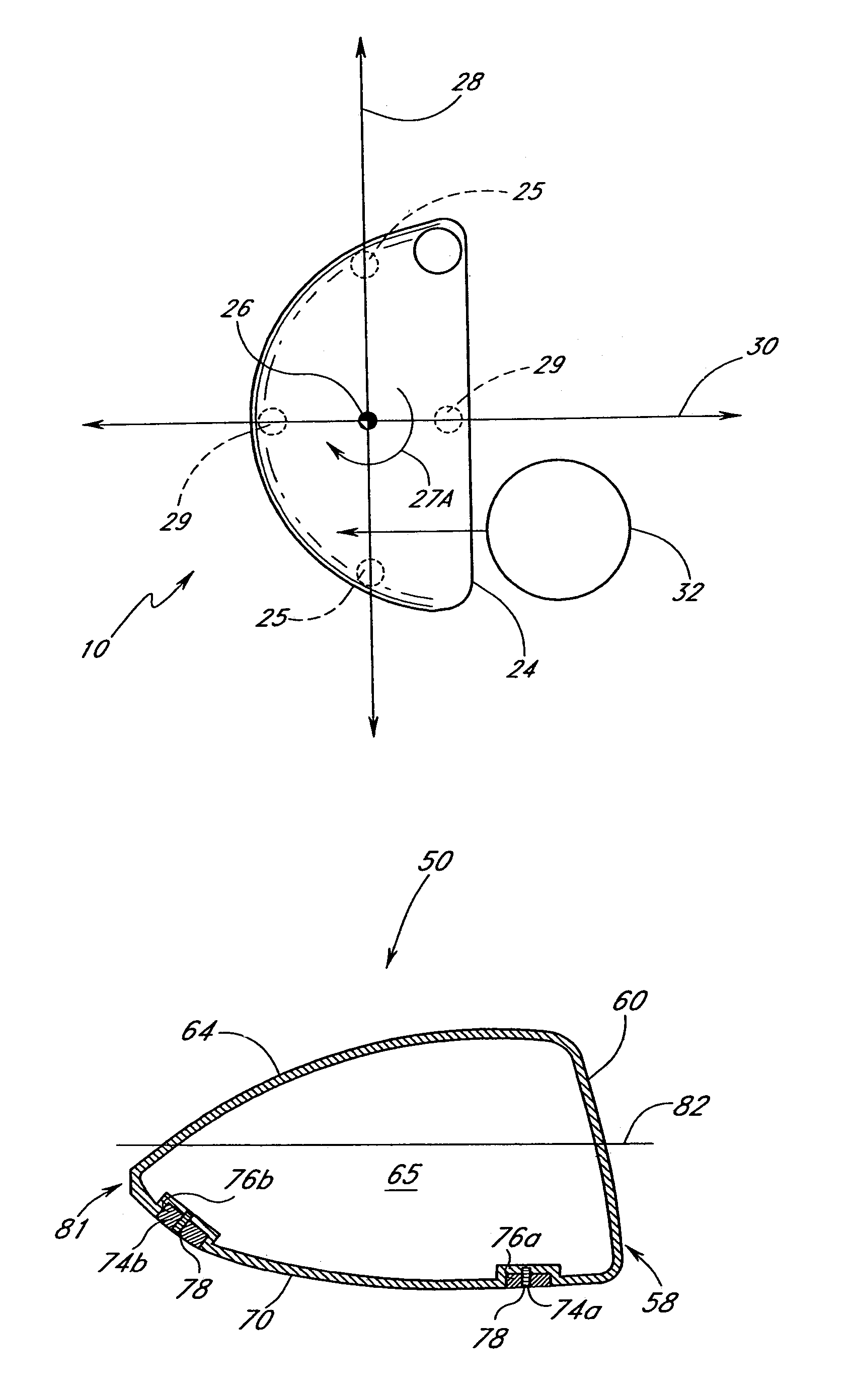
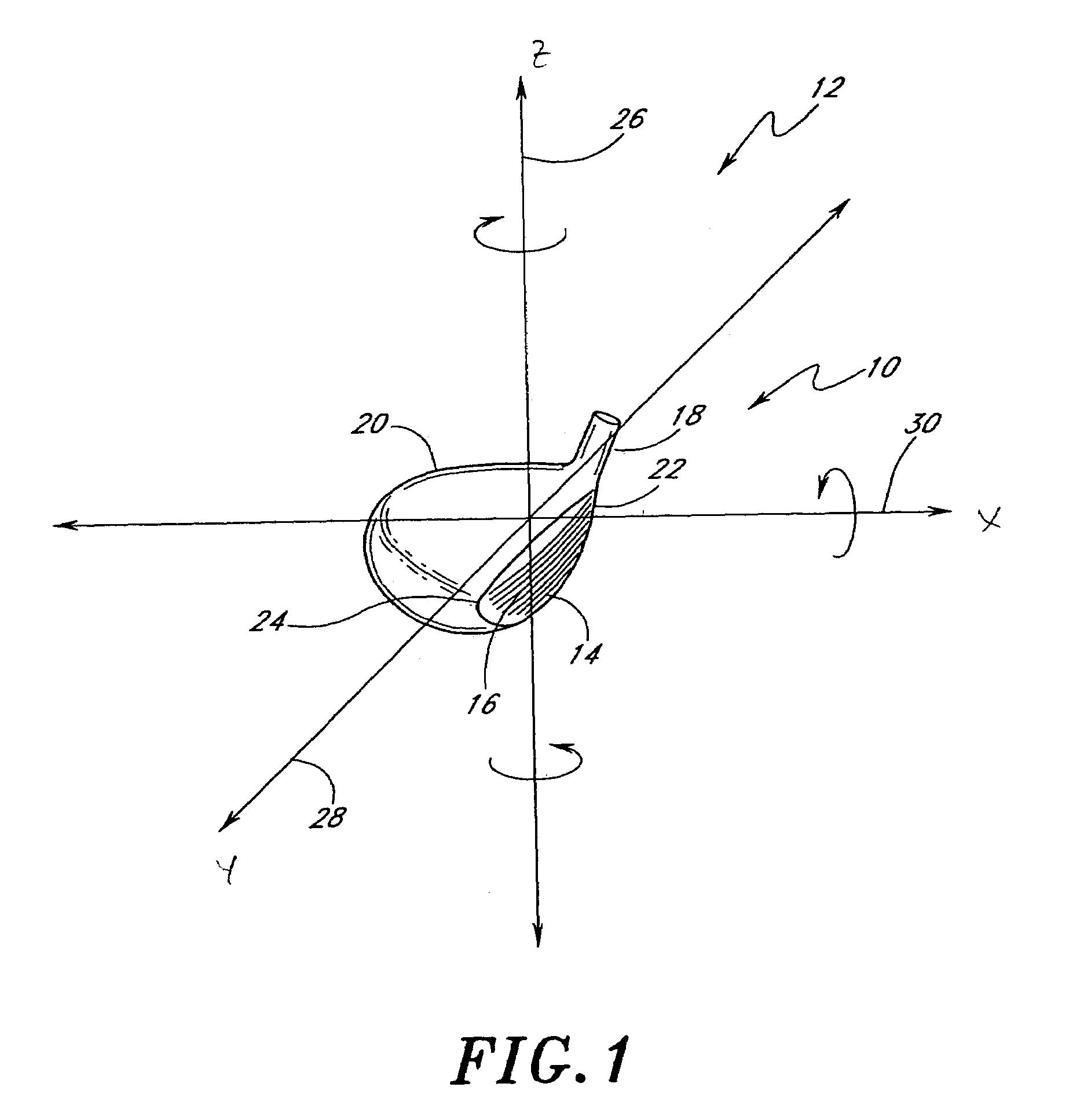
[0027]FIG. 1 is a perspective view of a club head 10 located about a coordinate system 12. The coordinate system 12 is centered about the center of gravity (“CG”) of the club head. As is typical in the art, the club head 10 comprises a strike plate 14, which defines a front surface or strike face 16 for impacting a golf ball. A hosel 18 extends upwardly from the strike plate 14. The hosel 18 is used to attach the club head 10 to a gold club shaft (not shown) as is well known in the art. The club head 10 also includes a load bearing outer shell 20 that is either integrally made with or attached to the strike plate 14. A heel region 22 of the club head 10 is located close to the hosel 18 while the toe region 24 so the club head is located opposite the heel region 22.

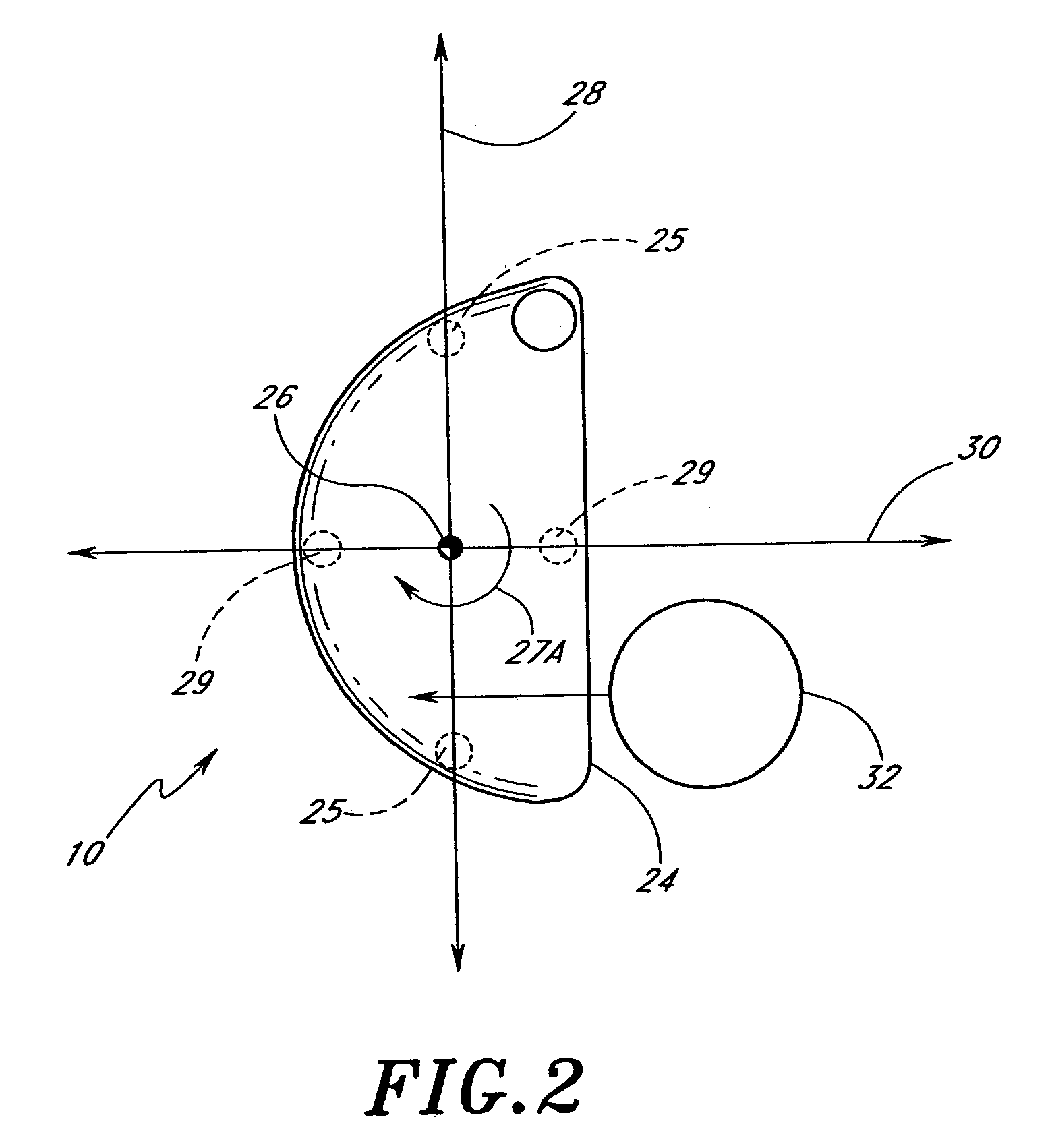
[0028]The coordinate system 12 comprises three axes:(i) a vertical axis 26 that extends through the CG generally parallel to the strike face 16 in a generally vertical direction relative to the ground when the club head 10...


PUM


Abstract

A golf club head comprising an outer shell and a strike plate having a strike face. The outer shell and the strike face define a club head volume. A heel / toe axis extends through the center of gravity of the club head. The heel / toe axis is generally parallel to the strike face and generally horizontal relative to a ground plane when the club head is at an address position. The rotational moment of inertia about the heel / toe axis is related to the club head volume by the equation Ixx ≧,46*HV+77, where Ixx is the rotational moment of inertia about the heel / toe axis in units of kg-mm2 and HV is the club head volume in units of cm3.

Description

CROSS-REFERENCE TO RELATED APPLICATION[0001]This application is a continuation of prior application Ser. No. 09 / 821,370, filed Mar. 29, 2001 now U.S. Pat. No. 6,991,558, which is herein incorporated by reference.BACKGROUND OF THE INVENTION[0002]1. Field of the Invention[0003]The present invention relates to golf clubs, and, in particular, to a golf club head with a designated relationship between the volume of the club head and the rotational inertia of the club head about a particular axis.[0004]2. Description of the Related Art[0005]A wood-type golf club typically includes a hollow shaft with a golf club head attached to the lower end of the shaft. The club head typically includes a load-bearing outer shell with an integral or attached strike plate. The strike plate defines a front surface or strike face adapted for striking a golf ball.[0006]The mass of a club head is limited by various practical considerations, such as the desire to keep the swing weight of the golf club close t...

Claims


Application Information

Patent Timeline
Patent Type & Authority Patents(United States)
IPC IPC(8): A63B53/04A63B53/06
CPCA63B53/04A63B53/0466A63B2053/0408A63B2053/0433A63B2053/0416A63B2053/0491A63B2053/0412A63B60/02A63B53/0408A63B53/0412A63B53/0416A63B53/0433A63B60/00
Inventor BEACH, TODD P.ANDERSON, DAVIDVINCENT, BENOIT
Owner TAYLOR MADE GOLF
Learn More