
Screen and screen frame for improved screen to shaker placement, handling and retention

Active Publication Date: 2007-05-01
MI
View PDF10 Cites 3 Cited by
  • Summary
  • Abstract
  • Description
  • Claims
  • Application Information

AI Technical Summary

Benefits of technology

[0003]In one illustrative embodiment, the support frame is designed such that the first lateral support brace and the second lateral support brace are positioned to form a wedge block clamping platform on the lateral edge of the support frame. In one preferred embodiment, the wedge block clamping platform is positioned and has a width such that it corresponds substantially to the width of the wedge block thereby enhancing screen clamping to the shaker.
[0004]Alternatively or in addition, an illustrative embodiment of the support frame is designed such that the combination of the first lateral support brace and the first and third outer lateral su

Problems solved by technology

Unfortunately, the shaking motion of the shaking separator can cause the loosening of

Method used


Image

  • Screen and screen frame for improved screen to shaker placement, handling and retention
  • Screen and screen frame for improved screen to shaker placement, handling and retention
  • Screen and screen frame for improved screen to shaker placement, handling and retention

Examples


Example

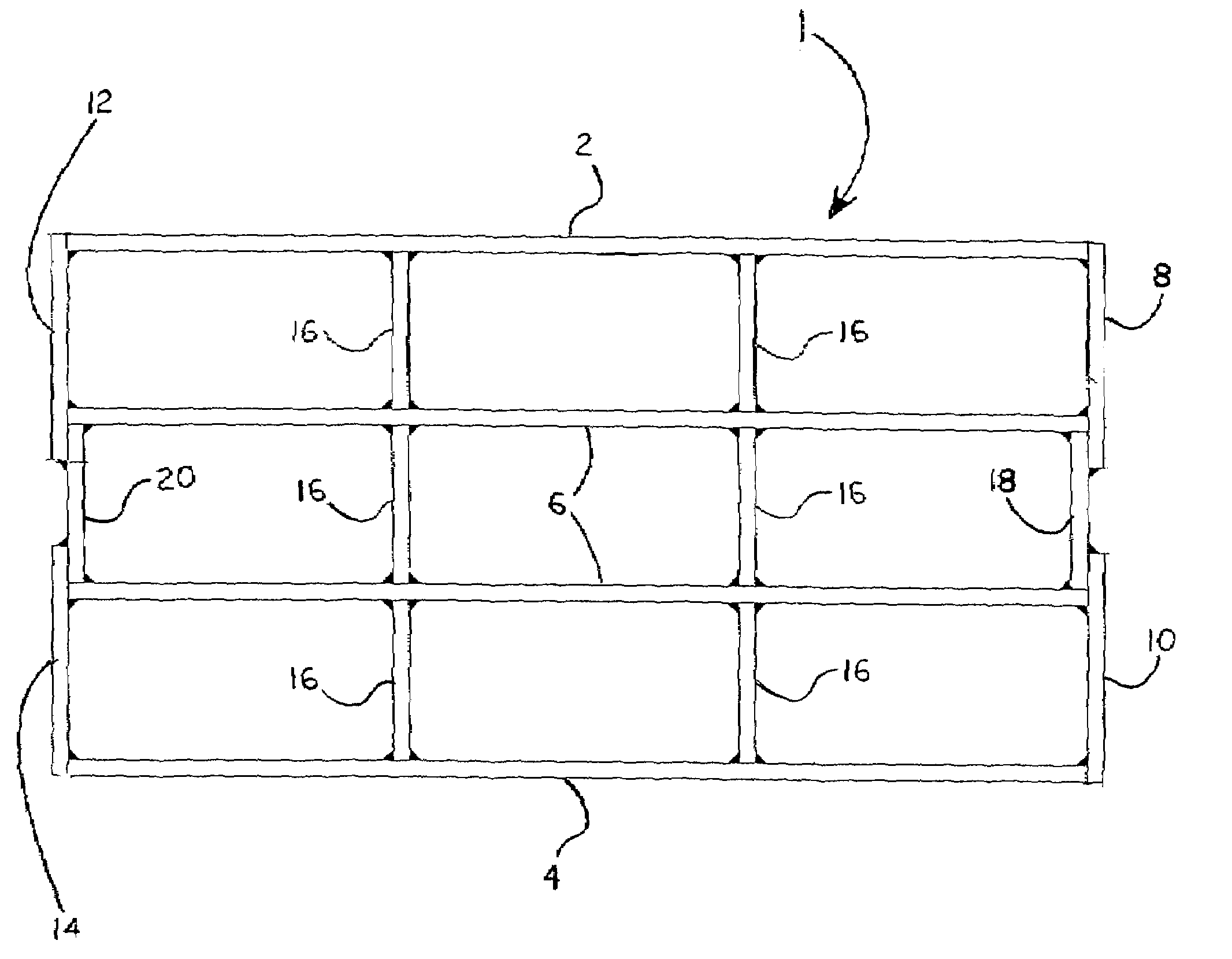
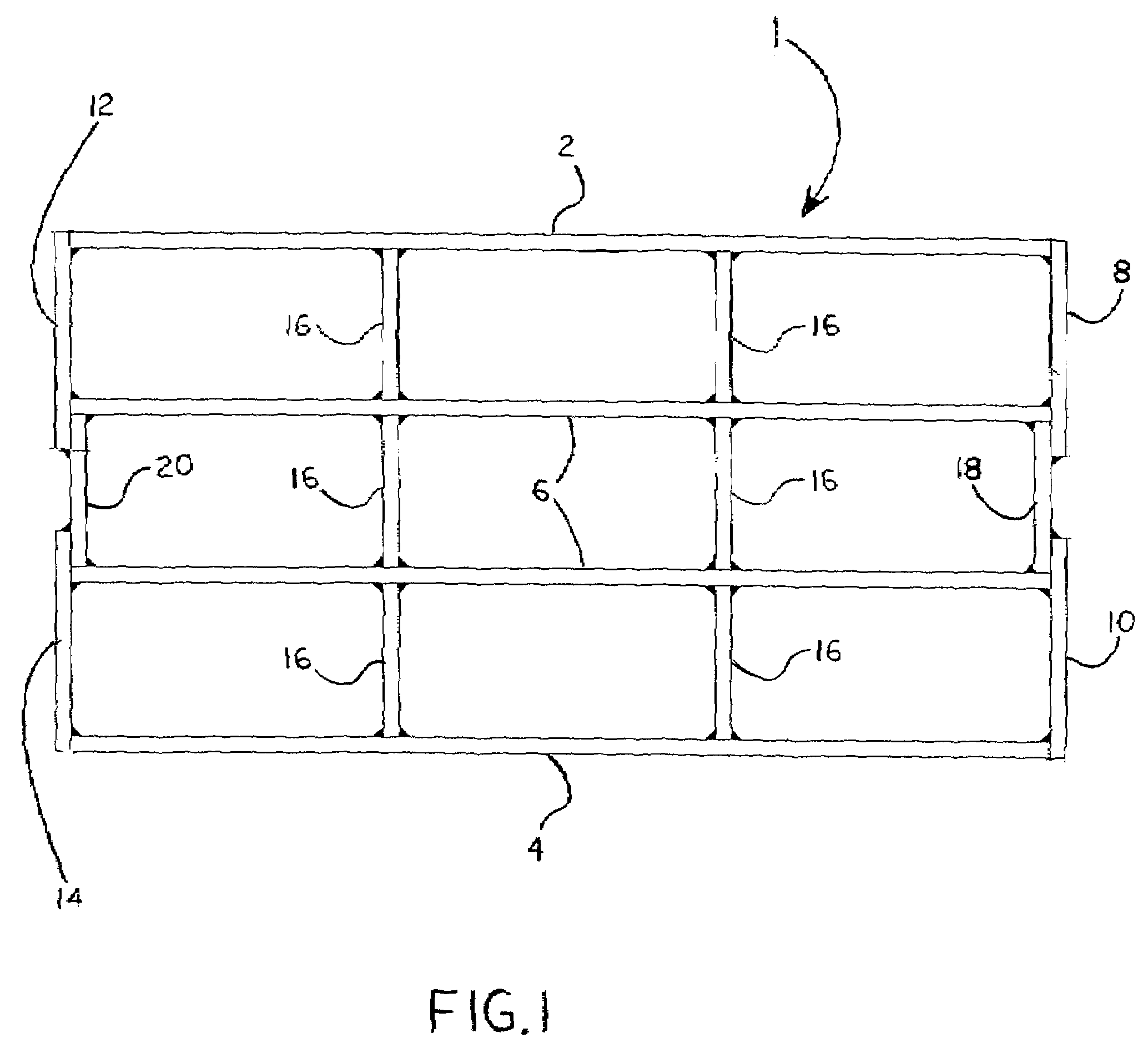
[0010]The present disclosure is generally directed to a support frame for a shaker screen and a shaker screen incorporating such a frame. With reference to FIG. 1, one illustrative embodiment of a frame for a shaker screen (1) of the present invention includes, a first outer longitudinal support member (2), and a second outer longitudinal support member (4), spaced apart from and substantially parallel to the other. It will be appreciated by one of skill in the art that all of the support members, unless noted otherwise, inherently have a first end and a second end. The frame also includes one or more inner longitudinal support member (6), each being positioned between and substantially parallel to the first outer longitudinal support member and the second outer longitudinal support member.

[0011]The frame further includes a first outer lateral support member (8), substantially perpendicular to the first outer longitudinal support member. One end of the first outer lateral support fr...


PUM


Abstract

A frame for a screen utilized in a shaker separator, the frame including: a first (2) and a second (4) longitudinal support member (2) spaced apart from and substantially parallel to the each other; one or more inner longitudinal support member (6), positioned between and substantially parallel to the outer longitudinal support members; a first (8) and a second (10) outer lateral support member (8), each being connected and substantially perpendicular to a corresponding outer longitudinal support member; a third outer lateral support member (12), connected and substantially perpendicular to the second outer longitudinal support member; a fourth outer lateral support member (14), connected and substantially perpendicular to the second outer longitudinal support member; one or more inner lateral support member (16), positioned between and substantially perpendicular to the first outer longitudinal support member and the second outer longitudinal support member and connected to the one or more inner longitudinal support member; a first lateral support brace (18), one end of which is connected to the first outer lateral support member and the other end of which is connected to the second end of the third outer lateral support member; a second lateral support brace (20), one end of which is connected to the second outer lateral support member and the other end of which is connected to fourth outer lateral support member.

Description

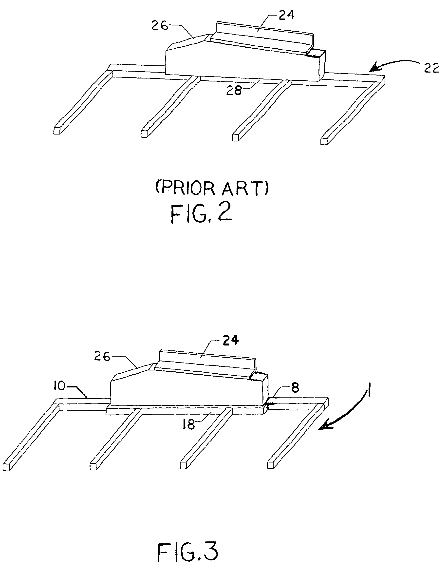
BACKGROUND[0001]Rotary drilling methods employing a drill bit and drill stems have long been used to drill wellbores in subterranean formations. Drilling fluids or muds are commonly circulated in the well during such drilling to cool and lubricate the drilling apparatus, lift drilling cuttings out of the wellbore, and counterbalance the subterranean formation pressure encountered. The recirculation of the drilling mud requires the fast and efficient removal of the drilling cuttings and other entrained solids from the drilling mud prior to reuse. Shaker separators are commonly used to remove the bulk solids from the drilling mud. An essential element of the shaker separators are the shaker screens. Shaker screens are typically composed of a support frame and screen (either pretensioned or perforated plate screen) assemblies. As is illustrated in FIG. 2 the current state of the art method for securing the shaker screen (22) to the shaker separator (not fully shown) involves the use of...

Claims


Application Information

Patent Timeline
IPC IPC(8): B07B1/46B07B1/49
CPCB07B1/46B07B2201/02
Inventor RIDDLE, RUSSELL
Owner MI
Learn More