Charging cable extraction device

Active Publication Date: 2019-03-28
DROST PAUL
View PDF1 Cites 2 Cited by
  • Summary
  • Abstract
  • Description
  • Claims
  • Application Information

AI Technical Summary

Benefits of technology

[0007]In accordance with the principles of the invention, as described fully below, the inventive instrumentation takes the form of a connection support cover that fits over the connecting end of the cable. The con

Problems solved by technology

While necessary, these cords have been found to lack in ruggedness, and repeated use (in terms of plugging into or removing from an embedded connector on a periphery of a device) has inevitably led to fraying of the cord, breaking of the cord (particularly at the connector), bent embedded connectors within the device, and the like.
Indeed, while most of these power cable

Method used


Image

  • Charging cable extraction device
  • Charging cable extraction device

Examples


Example

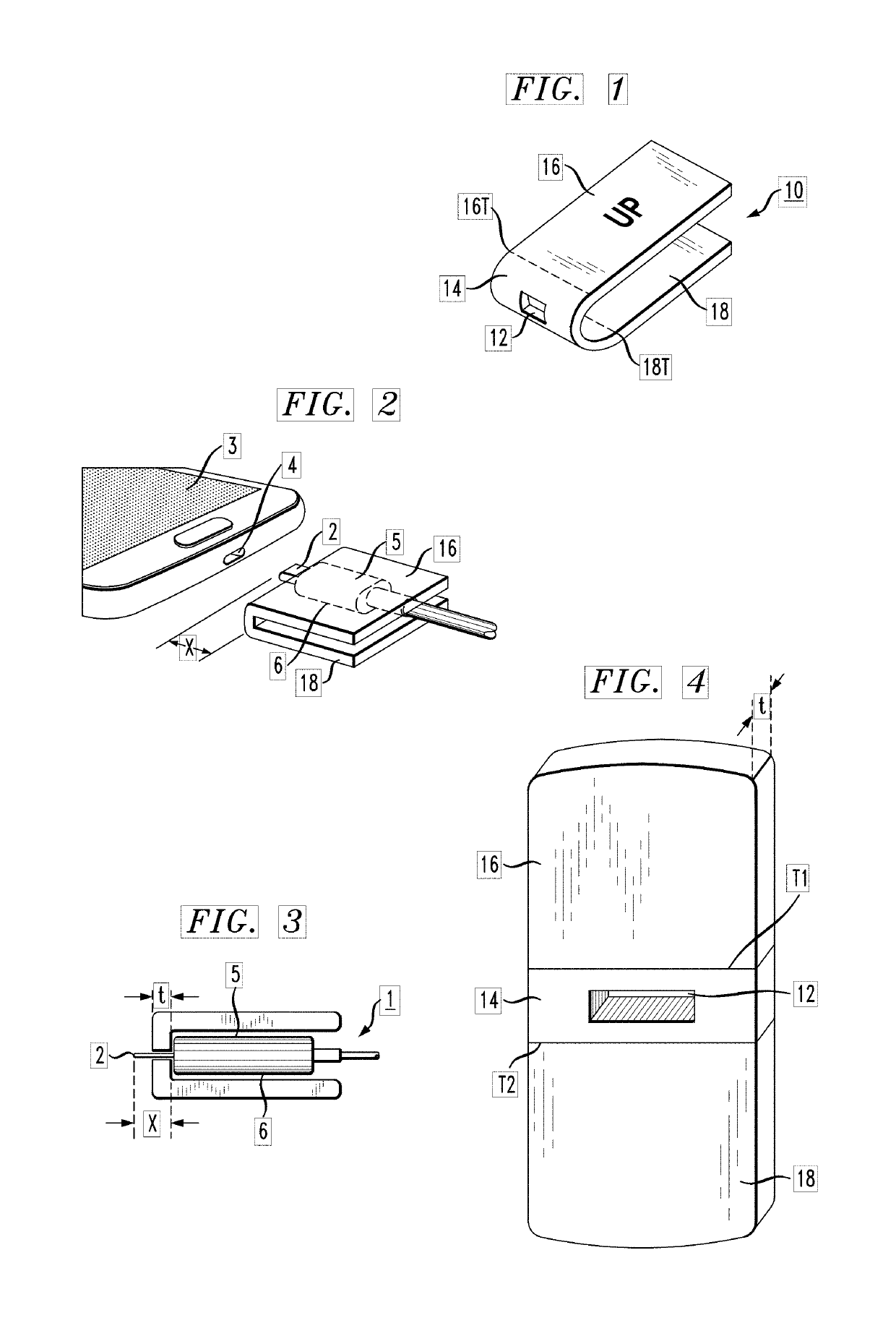
[0016]FIG. 1 is an isometric view of an exemplary connector support cover 10 formed in accordance with the present invention. Connector support cover 10 is shown as a generally U-shaped element, with an aperture 12 formed within an end portion 14. As also shown in FIG. 1, connector support cover 10 includes an upper grip arm 16 and a lower grip arm 18, attached to end portion 14 to form the general “U” shape. That is, upper grip arm 16 and lower grip arm 18 take the form of a pair of parallel sides, with end terminations 16T and 18T of arms 16 and 18, respectively, joining opposing end terminations T1 and T2 of end portion 14. In an exemplary embodiment, upper grip arm 16 and lower grip arm 18 are formed of a flexible material (e.g., low density plastic, laminated paper, or the like). It is to be understood that in a preferred embodiment of the present invention, the combination of end portion 14 and grip arms 16, 18 is configured as a unitary element and formed of a single piece of...


PUM


Abstract

A connection support cover is proposed that fits over the connecting end of the cable. The connection support cover is generally U-shaped and includes an aperture at the bottom of the U to allow for the actual connector portion of the cable to protrude through the cover. The connector support cover provides a larger, easier to grip surface and allows an individual to quickly and easily remove a cable from a device without harming either the cable or the embedded connector within the device.

Description

CROSS-REFERENCE TO RELATED APPLICATIONS[0001]This application claims the benefit of U.S. Provisional Application No. 62 / 562,677, filed Sep. 25, 2017 and herein incorporated by reference.TECHNICAL FIELD[0002]The present invention relates to chargeable electronic devices and, more particularly, to an instrumentation for providing repeatable insertion and removal of a charging cable with respect to the electronic device.BACKGROUND OF THE INVENTION[0003]The ubiquitous nature of electronic devices has led to the inevitable result that every device has its own power cable, used to re-charge the device (or at times simply used to provide power to a device as it is being used). From cellphones to tablets, electronic readers to gaming systems, each device may have a different type of power cable. Various ones currently include, but are not limited to: USB A-type, USB B-type, USB C-type, micro-USB A, micro-USB B, USB mini-b, etc.[0004]While necessary, these cords have been found to lack in ru...

Claims


Application Information

Patent Timeline
IPC IPC(8): H01R13/516H01R13/422H01R13/53
CPCH01R13/53H01R13/516H01R13/422H01R13/562H01R13/6335
Inventor DROST, PAUL
Owner DROST PAUL
Why Eureka
Try Eureka