Nail gun switch mechanism for switching dual actuation modes

a switch mechanism and nail gun technology, applied in the direction of manufacturing tools, nailing tools, stapling tools, etc., can solve the problems of easy accidental dangerous shot, easy to be wrongly actuated, and inability to permit a holding actuation mode, etc., to improve the safety ratio, reduce manufacturing costs, and be convenient to opera

Inactive Publication Date: 2007-05-08
DE POAN PNEUMATIC
View PDF12 Cites 45 Cited by
  • Summary
  • Abstract
  • Description
  • Claims
  • Application Information

AI Technical Summary

Benefits of technology

[0007]The nail gun switch mechanism utilizes the trigger lever and bias pole to improve the safety ratio, whatever the nail gun ...

Problems solved by technology

However the mechanism can not permit a holding actuation mode, which makes the nail gun is easily to be wrongly ac...

Method used


Image

  • Nail gun switch mechanism for switching dual actuation modes
  • Nail gun switch mechanism for switching dual actuation modes
  • Nail gun switch mechanism for switching dual actuation modes

Examples


Embodiment Construction

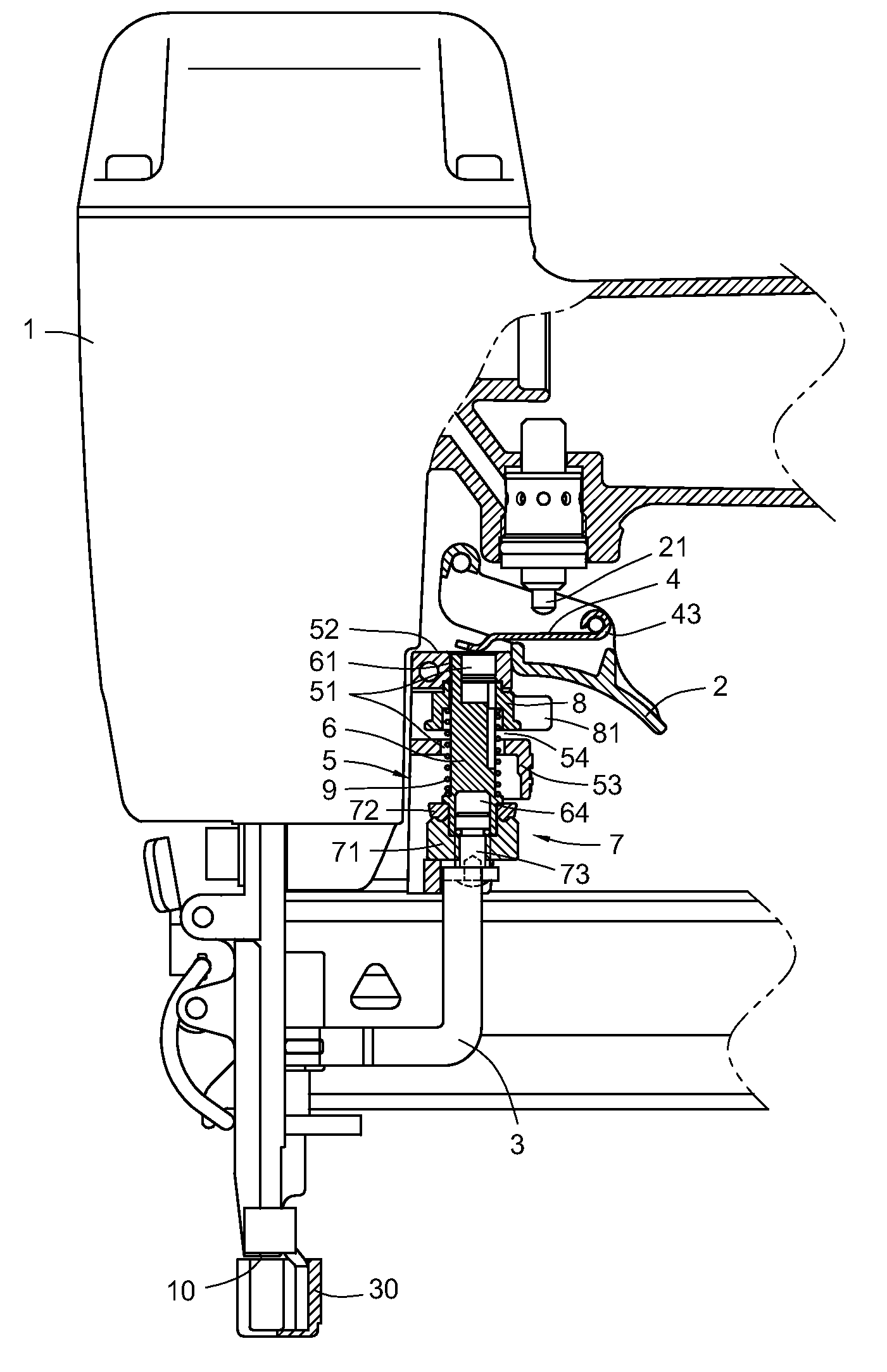
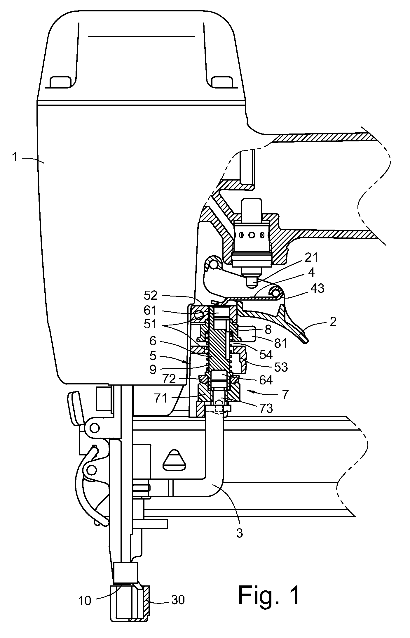
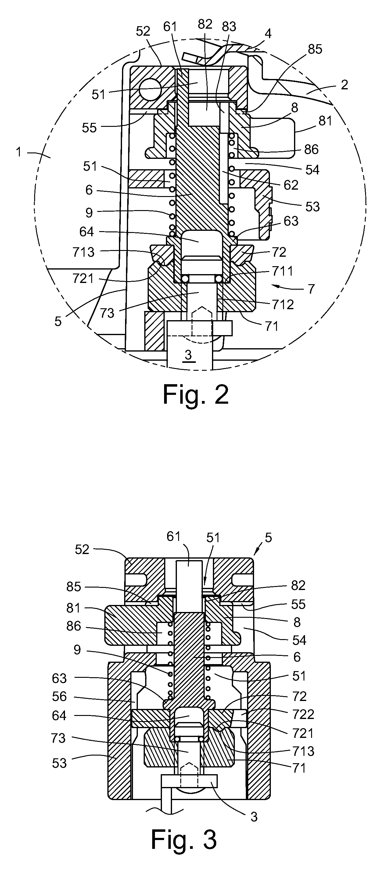
[0029]FIG. 1 discloses a nail gun switch mechanism according to a first embodiment of the present invention. The nail gun switch mechanism has a trigger 2 and a safety slidable bar 3 pivotally disposed on a gun body 1. The nail gun switch mechanism further has a trigger valve bar 21 received in the trigger 2, a trigger lever 4 pivotally disposed thereon, a longitudinally guiding hole 51 formed at a peripheral side of the gun body 1 between the safety slidable bar 3 and the trigger 2, a shaft 6 slidably received in the longitudinally guiding hole 51 (as shown in FIGS. 2 to 3).

[0030]The trigger lever 4 has a pivot base 43 (as shown in FIG. 4) pivotally disposed on the trigger 2. When the trigger lever 4 is pushed or is brought to upwardly move (as shown in FIG. 7), an intermediate portion of the trigger lever 4 can push the trigger valve bar 21.

[0031]The safety slidable bar 3 has a bend shape (as shown in FIG. 1). One end of the safety slidable bar 3 connects with the shaft 6 (referri...


PUM

PropertyMeasurementUnit
Deformation enthalpyaaaaaaaaaa

Abstract

A nail gun switch mechanism has a trigger valve bar received in a trigger of the nail gun; a trigger lever pivotally disposed on the trigger; a safety slidable bar pivotally disposed on a gun body; a longitudinal guiding hole formed at a peripheral side of the gun body; a shaft slidably received in the guiding hole; a switch bar arranged on the shaft, which the switch bar can bring the shaft to rotate in the longitudinally guiding hole; and a hitting base of the safety slidable bar extending out from an hitting mouth formed at a bottom portion of the gun body. The shaft has a bias pole disposed at a top portion thereof, which the bias pole can synchronously rotate with the shaft and can be reposited by the adjusting of the switch bar. The trigger lever has a shorter end portion; a longer end portion; and an opening.

Description

BACKGROUND[0001]The present invention relates to a nail gun switch mechanism, and particularly to a nail gun switch mechanism for switching the nail gun operation in a sequential actuation mode, a contact actuation mode, or a holding actuation mode.[0002]Actuating nails for a pneumatic nail gun generally can be divided into two kinds, one is the sequential actuation mode (or the restrictive mode) and the other is the contact actuation mode.[0003]The sequential actuation mode means the operator firstly should set a safety slidable bar or a hitting base on the safety slidable bar contacting on a workpiece to push an upward movement of a trigger lever, and then press a trigger to bring the trigger lever to actuate a trigger valve. In this mode, if the operator wants to actuate again, he should release the trigger first, and then repeat the processes of pressing the trigger. If the operator disobeys the operating sequence, i.e. first pressing the trigger and then pressing the safety sli...

Claims


Application Information

Patent Timeline
IPC IPC(8): B25C1/04
CPCB25C1/008
Inventor WEN, WAN-FU
Owner DE POAN PNEUMATIC
Why Eureka
Try Eureka