Spring energized stapler lever fulcrum in low position

a lever fulcrum and energized technology, applied in the field of desk staplers, can solve the problems of limited total vertical motion of the striker and high ris

Active Publication Date: 2007-05-15
WORKTOOLS
View PDF48 Cites 16 Cited by
  • Summary
  • Abstract
  • Description
  • Claims
  • Application Information

AI Technical Summary

Benefits of technology

[0006]In the present invention a lever pivots about a lowest possible fulcrum position so that the lever front end is as high as possible above the fulcrum when the lever is at the release point. As discussed above, this design tends toward a reliable release condition. According to the invention a lever and flat power spring share a fulcrum post. The fulcrum post includes a flat rear face that extends down to be adjacent to the power spring. Near the release point the lever presses this flat face at a location immediately adjacent to the spring. The lever pivot is then in the lowest possib

Problems solved by technology

If the release is too early the striker will not raise high enough to allow the s

Method used


Image

  • Spring energized stapler lever fulcrum in low position
  • Spring energized stapler lever fulcrum in low position
  • Spring energized stapler lever fulcrum in low position

Examples


Embodiment Construction

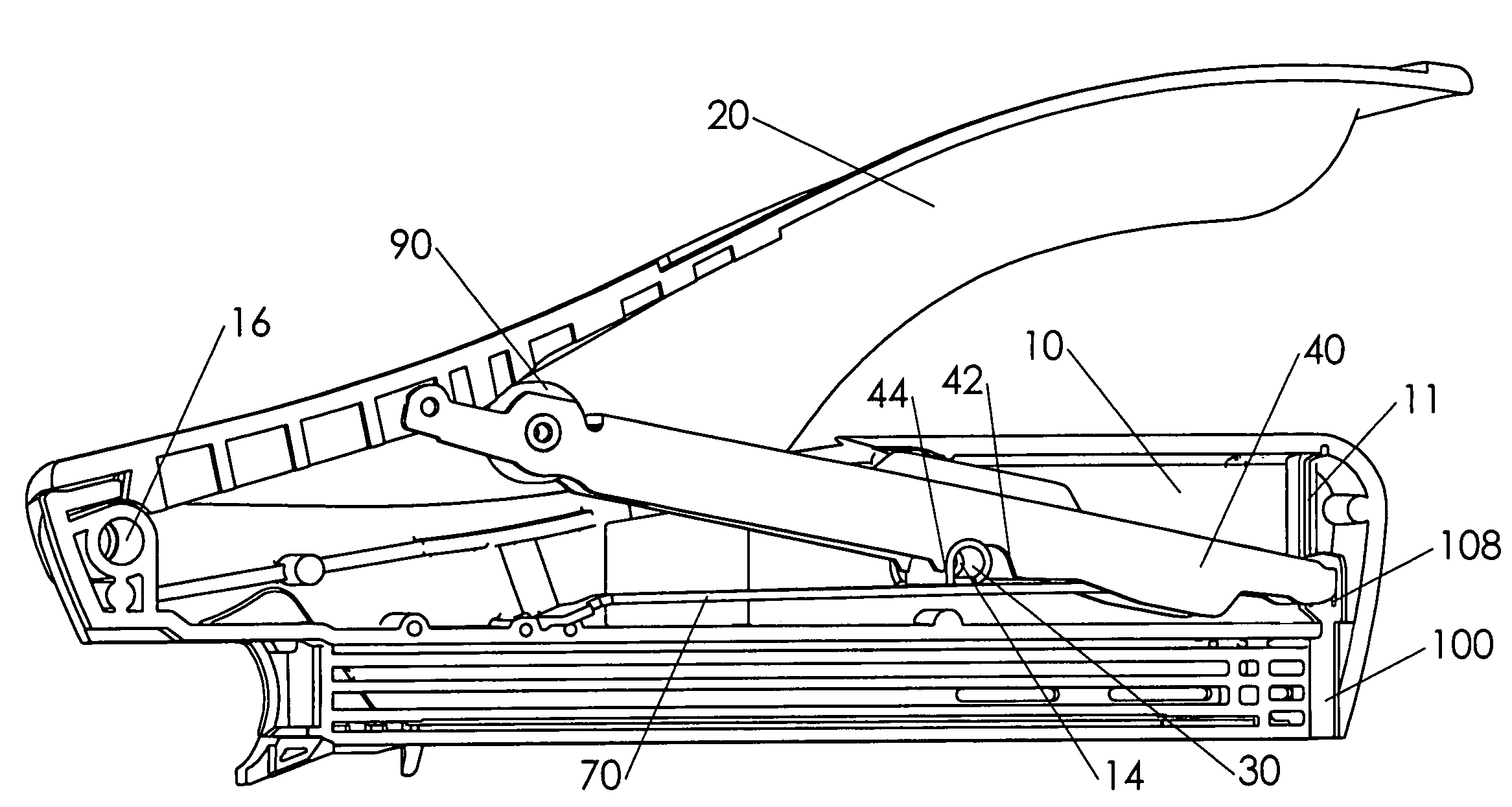
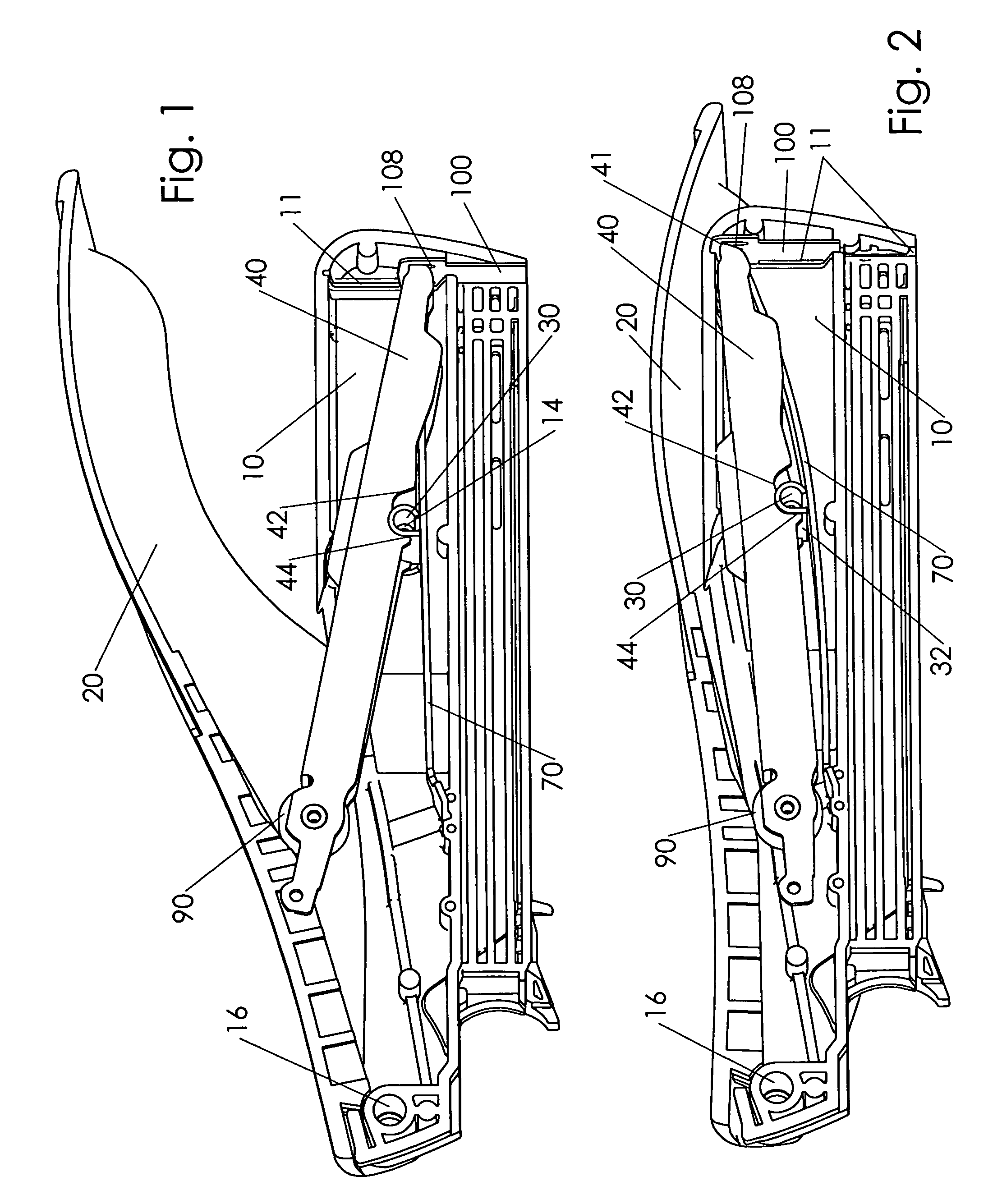
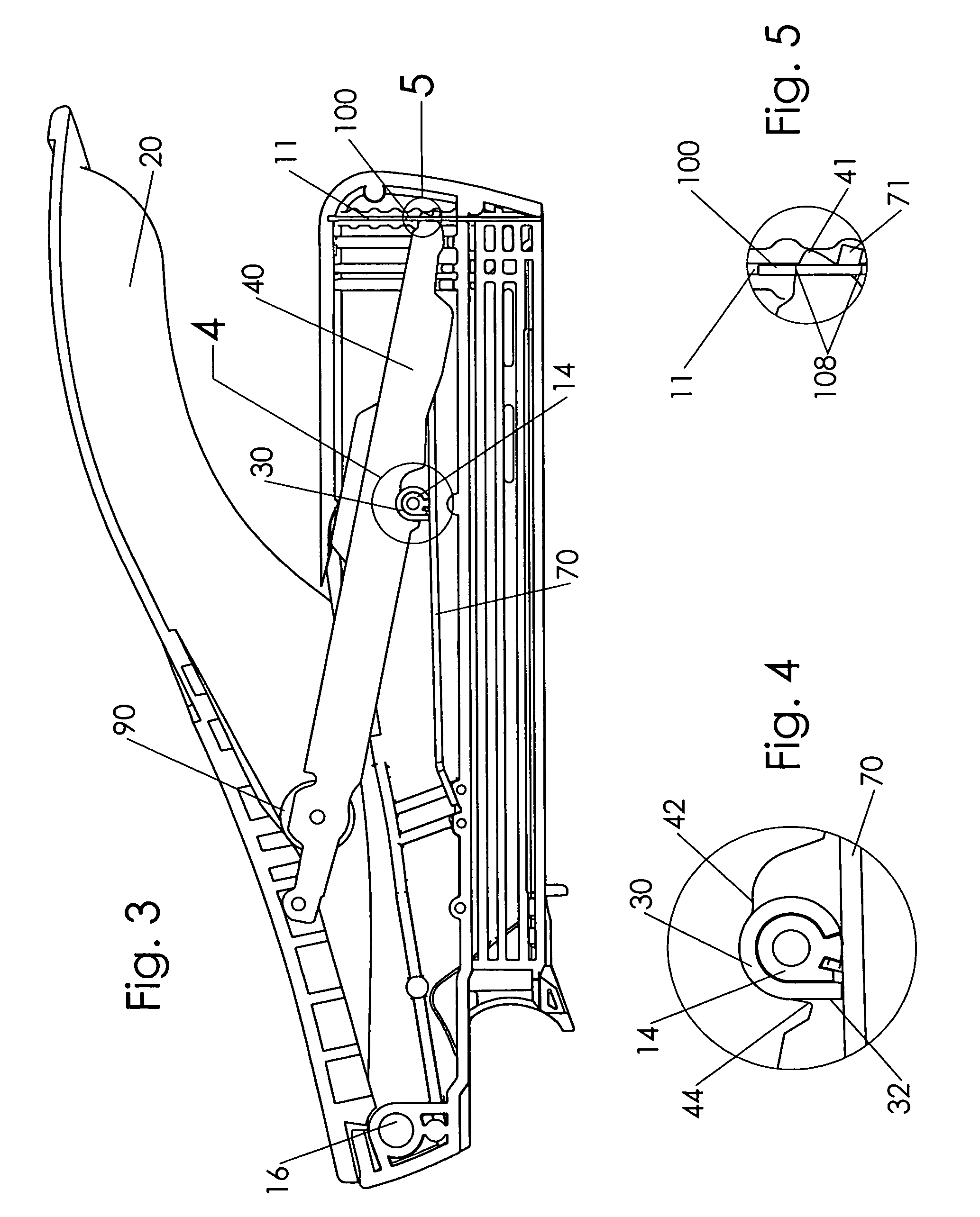
[0018]In the Figures only selected parts of a stapler are shown for clarity. These include left housing half 10, handle 20, lever 40, fulcrum sleeve 30, power spring 70, wheel 90, and striker 100. Striker 100 is vertically movable within housing 10. FIGS. 1 and 3 show these components of the stapler in an initial rest position. Handle 20 is linked to lever 40 through optional low friction wheel 90. As handle 20 is pressed the mechanism approaches the configuration of FIGS. 2 and 6. Lever 40 is forced to rotate counterclockwise so that release end 41 of the lever moves upward. Power spring 70 engages an opening, not shown, in striker 100 at spring tip 71, FIGS. 5 and 8. Power spring 70 deflects about fulcrum sleeve 30. Fulcrum sleeve 30 surrounds fulcrum post 14 of housing 10. A “lever fulcrum” refers generally to the fulcrum position defined by the location on fulcrum sleeve 30 that lever 40 pivots. Lever release end 41 moves in an arcing motion about the lever fulcrum. As the lever...


PUM


Abstract

A spring actuated stapler includes a lever releasably linked to a striker at a lever front end. An elongated power spring is linked to the striker so that raising the lever front end deflects the power spring. The lever and power spring pivot about a common fulcrum structure. The fulcrum structure includes a rear facing surface and the lever pivots about the rear facing surface when the lever is near a lever release point. This pivot location is adjacent to the power spring, at a bottom of the structure of the fulcrum. With the lowest possible pivot location the lever retracts and releases from the striker more quickly than if the lever pivots about a higher location at a fulcrum “axial center”. The release action is therefore more consistent, and less sensitive to manufacturing variations of the stapler.

Description

FIELD OF THE INVENTION[0001]The present relates to desktop staplers. More precisely the present invention relates to geometry of a pivotal mounting of an actuating lever within a spring-powered stapler.BACKGROUND OF THE INVENTION[0002]In a common spring powered stapler a handle is linked to a rear end of a lever, and the front end of the lever is linked to a striker. Pressing the handle causes the lever to pivot about a lever fulcrum. According to one design the front end of the lever moves upward in an arcing motion so that the lever moves rearward as the lever front end approaches its upper limit. At a predetermined position of the lever the striker is disengaged from the lever. The striker then moves downward from the bias of a power spring to eject a staple from the stapler.[0003]U.S. Pat. No. 5,988,478 (Marks) shows a lever and a power spring where each respective component has a separate and distinct fulcrum. U.S. Pat. No. 6,145,728 (Marks) shows a staple gun where a power spr...

Claims


Application Information

Patent Timeline
IPC IPC(8): B25C5/06
CPCB25C5/11B25C5/0242
Inventor MARKS, JOEL S.
Owner WORKTOOLS
Why Eureka
Try Eureka