Tube coupling for ink jet cartridges

Inactive Publication Date: 2007-05-22
NU KOTE INT
View PDF7 Cites 0 Cited by
  • Summary
  • Abstract
  • Description
  • Claims
  • Application Information

AI Technical Summary

Benefits of technology

[0004]In accordance with the present invention, a coupling is provided for connecting flexible ink supply tubing to an ink cartridge which optimizes achieving a leak-tight connection between the cartridge and coupling. The coupling has threaded interengagement with a wall component of the ink chamber in a cartridge such that the interengaging threads are in tension to optimize sealing engagement therebetween and, accordingly, a leak-tight joint between the ink chamber and the exterior of the cartridge. Preferably, the coupling component is provided with a flange adjacent a threaded stem of the coupling which engages the outer side of the wall component of the ink chamber to provide a further seal against leakage as the threaded interengagement between the stem and wall pulls the flange into tight engagement with the outer side of the wall. It is also preferred to provide for the coupling to have an outer leg parallel to the outer side of the cartridge for connection with the supply tubing. This configuration advantageously provides for the tubing to be closely adjacent the outer side of the cartridge and positioned for connection with the cartridge or an attachment thereto to provide strain relief for the tubing.

Problems solved by technology

In the latter arrangement, it is possible to unintentionally separate the coupling components so as to expose ink in the cartridge to spillage.
Moreover, at least upon continued usage, wear of the slidably interengaging components could result in creating a leakage path or paths from the interior to the exterior of the cartridge.
A coupling of the ink supply tube to an opening into the cartridge by gluing the tubing in place is of course subject to the creation of a leakage path across the glue in response to lateral flexure of the supply tube relative to the cartridge and / or as a result of tension applied to the tubing in the direction outwardly or inwardly of the cartridge.

Method used


Image

  • Tube coupling for ink jet cartridges
  • Tube coupling for ink jet cartridges

Examples


Embodiment Construction

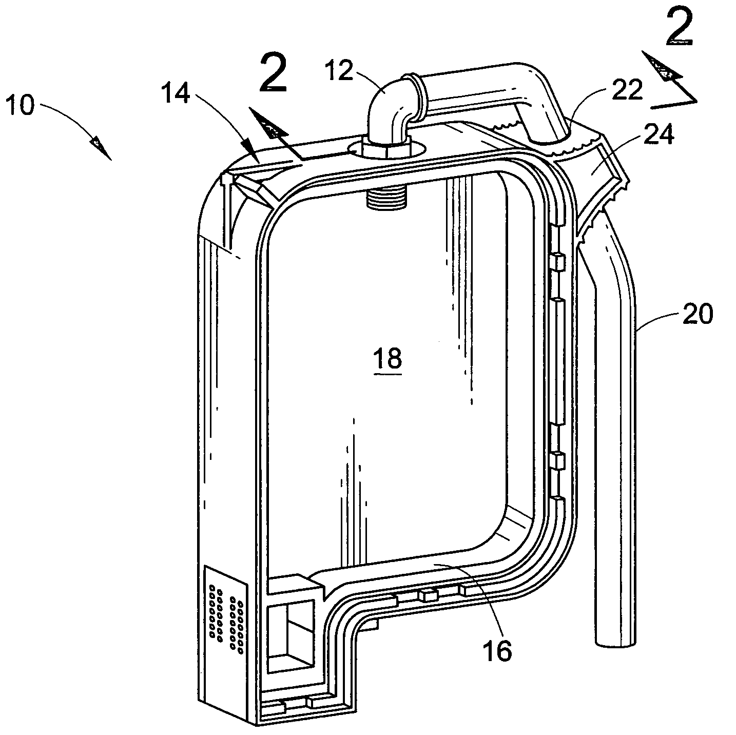
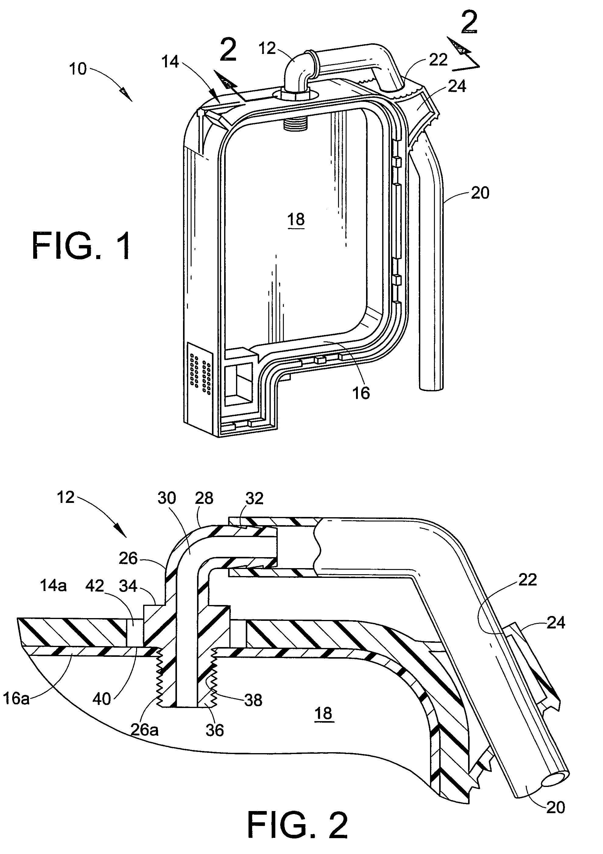
[0008]Referring now in greater detail to the drawings, wherein the showings are for the purpose of illustrating a preferred embodiment of the invention only and not for the purpose of limiting the invention, FIG. 1 illustrates, in part, an ink cartridge 10 on which a tubing coupling 12 according to the invention is mounted. Cartridge 10 comprises an outer plastic housing 14 and an inner plastic frame 16. While not shown, sheets of foil are attached to the opposite edges of the inner plastic frame to create a bag-like assembly that holds the cartridge ink, and the latter assembly is received within the outer plastic housing but is not attached thereto. Further, while not shown, metal side plates are assembled to the outer plastic housing to complete the outer enclosure for the cartridge. The latter ink cartridge construction is well known in the art. As will be appreciated from the cartridge structure, the area within inner frame 16 provides an ink chamber 18, and in a continuous ink...


PUM


Abstract

An ink jet cartridge comprising an outer housing and an inner ink chamber has adjacent housing and chamber wall portions, and a coupling member for communicating the ink chamber with an external source of ink has an inner end extending through an oversized opening in the housing wall portion and into threaded interengagement with an opening through the chamber wall portion. The outer end of the coupling is outside the housing wall portion for connection to a source of ink.

Description

BACKGROUND OF THE INVENTION[0001]This invention relates to the art of ink cartridges for ink jet printers and, more particularly, to an improved coupling device for connecting an ink supply line to an ink cartridge in a continuous ink supply system.[0002]Continuous ink refill systems for disposable ink jet cartridges are of course well known as shown, for example, in U.S. Pat. No. 5,469,201 to Erickson, et al. and U.S. Pat. No. 5,745,137 to Scheffelin, et al., both of which are incorporated herein by reference for background information. In such systems, basically, a cartridge is connected to an auxiliary ink supply reservoir by means of a flexible hose or tube, and during operation of the printing system, the tube is open to allow ink to flow from the auxiliary reservoir to the ink cartridge. During shipment or handling of the ink supply reservoir / cartridge system when it is outside the print machine, it is important that the connection of the tube to the cartridge be leak tight to...

Claims


Application Information

Patent Timeline
IPC IPC(8): B41J2/175
CPCB41J2/17509
Inventor HOLLAND, CARL W.PUTMAN, WILLIAM A.
Owner NU KOTE INT
Why Eureka
Try Eureka