
Adjustable dumbbell

Inactive Publication Date: 2007-05-29
CHEN PAUL
View PDF8 Cites 67 Cited by
  • Summary
  • Abstract
  • Description
  • Claims
  • Application Information

AI Technical Summary

Benefits of technology

[0010]The primary objective of the present invention is to provide an adjustable dumbbell assembly including an easily and quickly adjustable structure.

Problems solved by technology

However, the weight rings or weight members may not be solidly secured to the shaft while in use.

Method used


Image

  • Adjustable dumbbell
  • Adjustable dumbbell
  • Adjustable dumbbell

Examples


Embodiment Construction

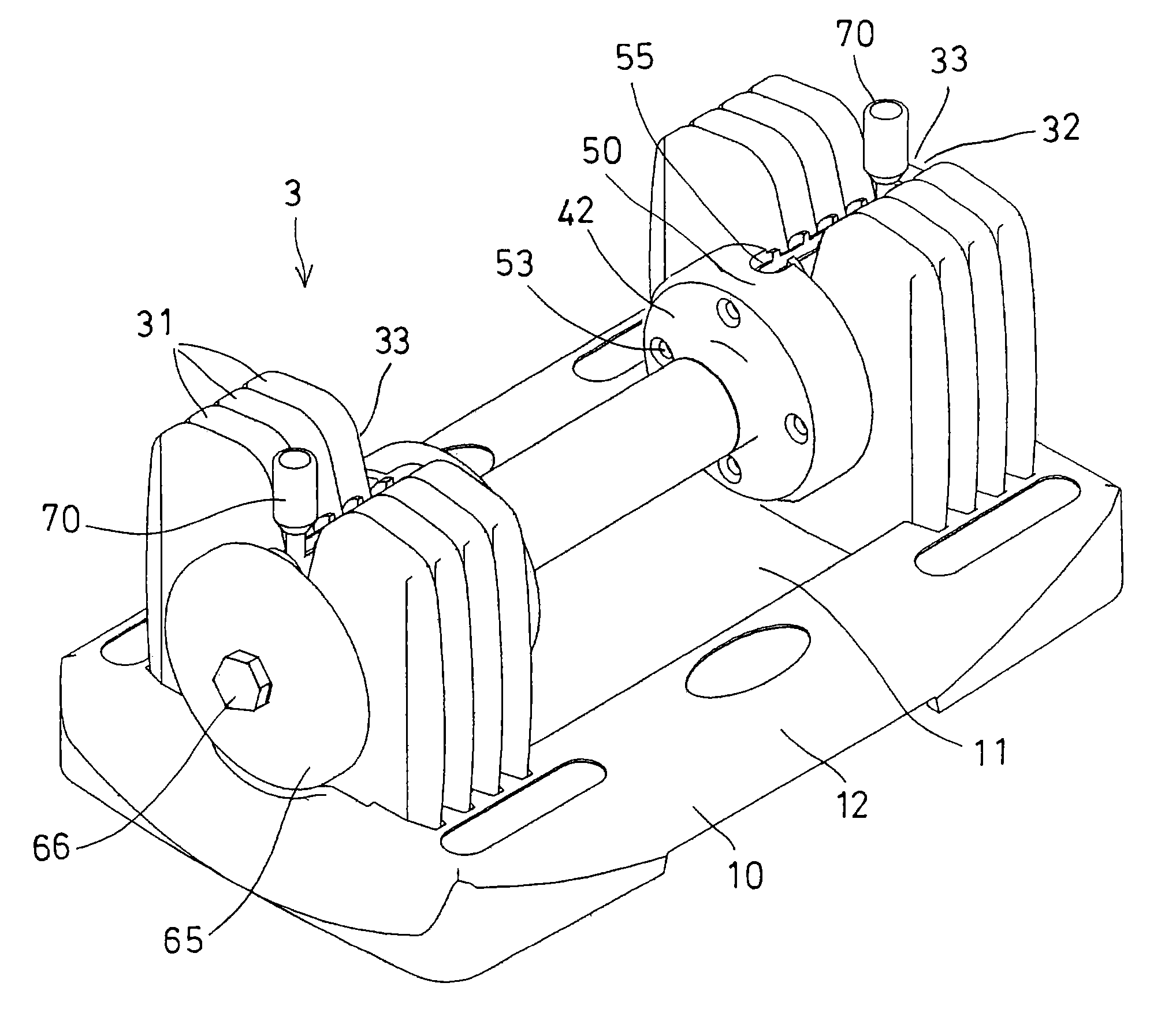
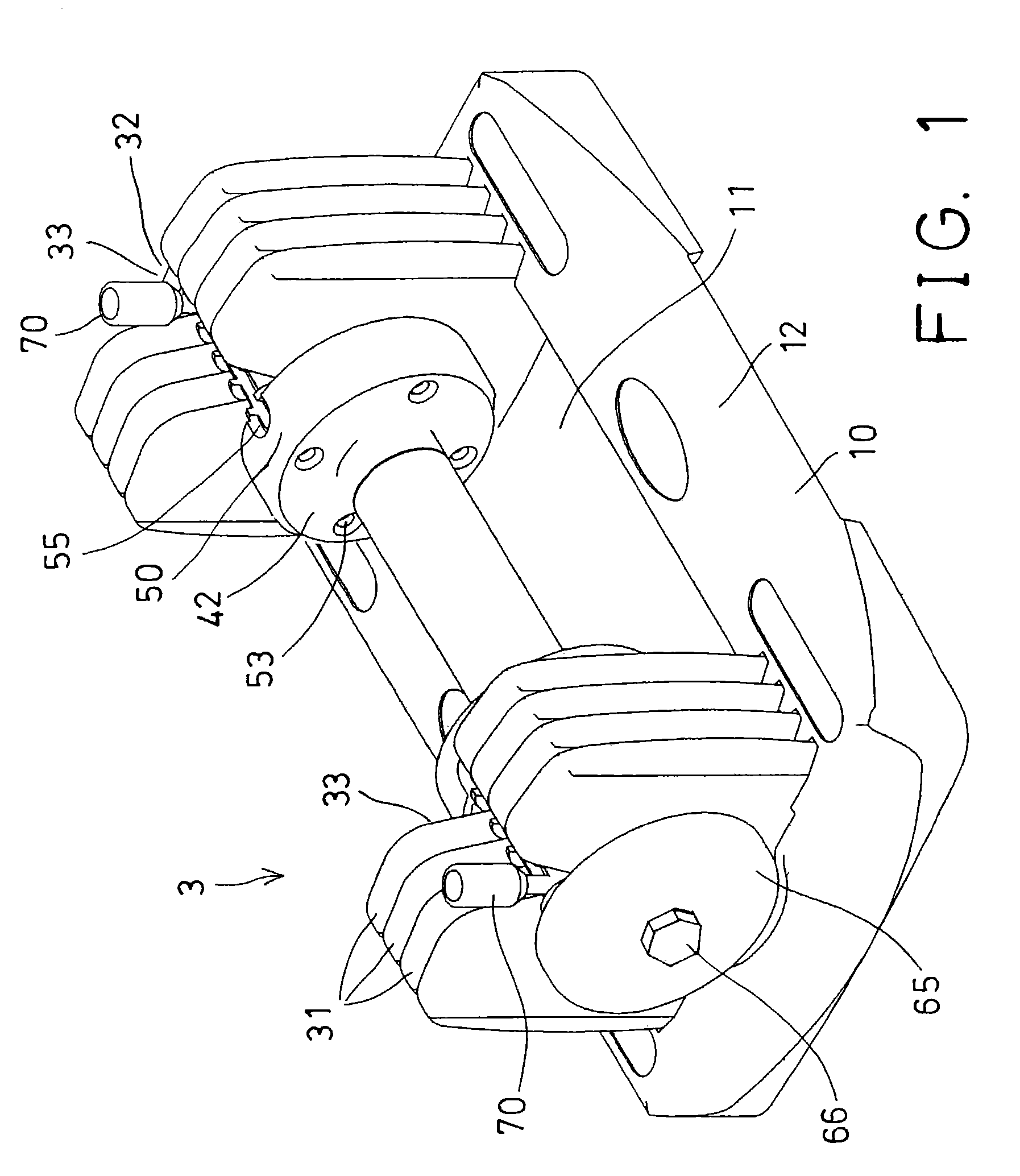
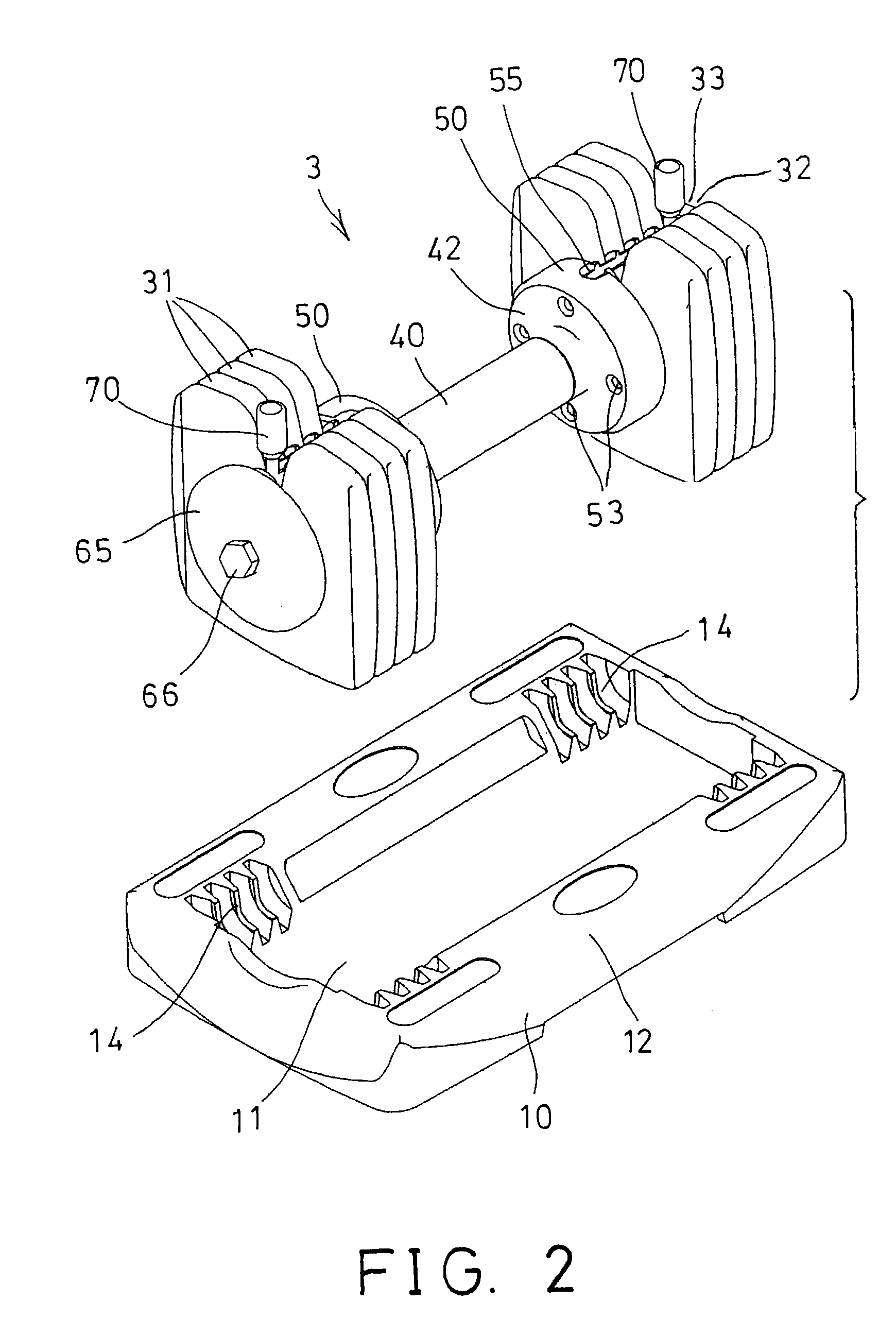
[0025]Referring to the drawings, and initially to FIGS. 1–5, an adjustable dumbbell assembly in accordance with the present invention comprises a base 10 including a recess 11 formed therein and defined by two side bulges 12, for receiving or supporting a dumbbell device 3 therein. Each of the bulges 12 of the base 10 includes a number of socket depressions 14 formed therein.

[0026]The dumbbell device 3 includes a number of weights 31 each having a lower portion engageable or receivable in the socket depressions 14 of the base 10, for allowing the weights 31 to be stably and erectly supported on the base 10. However, the lower portions of the weights 31 may also be arranged to be erectly supported on ground without the base 10.

[0027]Each of the weights 31 includes a groove, such as a vertical groove 32 formed therein and having an open top 33, and includes a lateral channel 34 formed therein and communicating with or intersecting with the vertical groove 32 thereof. The lateral chann...


PUM


Abstract

An adjustable dumbbell device includes a handle, a number of weights each having a channel to slidably receive an end portion of the handle, and a latch slidably engaged onto the end portion of the handle and engageable into the channels of a selected number of the weights, to secure the selected number of the weights to the end portion of the handle. A securing device may be used for securing the latch to the end portion of the handle, and includes one or more beams attached to the end portion of the handle, and a spring biasing catch may catch the latch to the beams or the end portion of the handle.

Description

[0001]The present invention is a continuation-in part of U.S. patent application Ser. No. 09 / 867,509, filed on May 31, 2001, now U.S. Pat. No. 6,656,093.BACKGROUND OF THE INVENTION[0002]1. Field of the Invention[0003]The present invention relates to an adjustable dumbbell, and more particularly to an adjustable dumbbell assembly having an easily and quickly adjustable structure.[0004]2. Description of the Prior Art[0005]Various kinds of typical adjustable dumbbells have been developed. U.S. Pat. No. 4,566,690 to Schook, and U.S. Pat. No. 5,407,413 to Kupferman disclose two of the typical dumbbells each including one or more weight rings that may be selectively or adjustably secured together for adjusting the weight of the dumbbells.[0006]In U.S. Pat. No. 4,566,690 to Schook, the weight rings each includes an outer thread for threading with the inner threads of the other weight rings and for securing the weight rings together. It takes time to thread the weight rings together.[0007]I...

Claims


Application Information

Patent Timeline
IPC IPC(8): A63B21/072A63B21/075A63B21/062
CPCA63B21/075A63B2021/0623A63B21/063
Inventor CHEN, PAUL
Owner CHEN PAUL
Learn More