
Power-supply device

a power supply device and power supply technology, applied in the direction of coupling device connection, cable arrangement between relatively moving parts, cable, etc., can solve the problems of troublesome work to return the slider b>, large noise, etc., and achieve the effect of preventing the deformation of the resilient part by the cres

Inactive Publication Date: 2007-07-03
YAZAKI CORP
View PDF12 Cites 23 Cited by
  • Summary
  • Abstract
  • Description
  • Claims
  • Application Information

AI Technical Summary

Benefits of technology

The present invention provides a power-supply device with a curved wire harness that is routed out from a case and expanded and contracted through a slider. The slider is mounted on a guide rail and is slidable along the guide rail. An urging member with a resilient part is mounted on the slider and is resiliently engaged with the guide rail. The resilient part is positioned stably and prevents deformation when the slider is stopped. The urging member is slidably engaged with the slider and is resiliently engaged with the guide rail when the slider is moved. The resilient part is formed in a bent plate shape to smoothly move over the guide rail. The crests and troughs of the guide rail form a corrugated part that allows the resilient part to move smoothly. The technical effects of the invention include stable positioning of the resilient part and prevention of deformation, smooth movement of the resilient part along the guide rail, and secure and smooth slidation of the resilient part when the slider is stopped.

Problems solved by technology

Further, when the sliding door is opened or closed and the slider 65 is moved along the guide rail 66, the rattle may cause the abrasion, and make a larger noise.
Thereby, a troublesome work to return the slider 65 to a predetermined position may be generated.

Method used


Image

  • Power-supply device
  • Power-supply device
  • Power-supply device

Examples


first embodiment

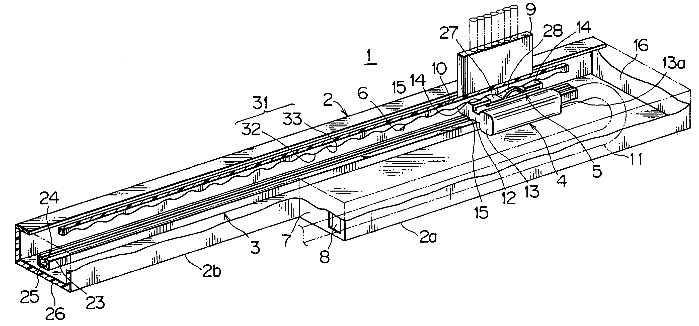
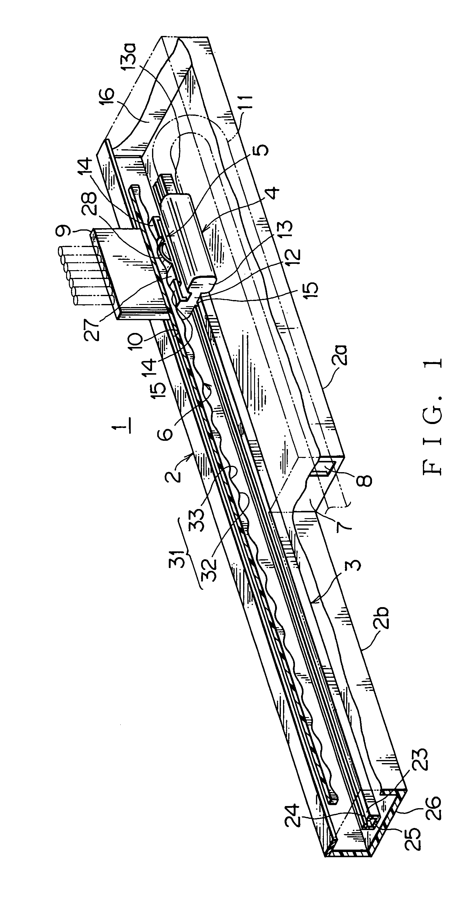
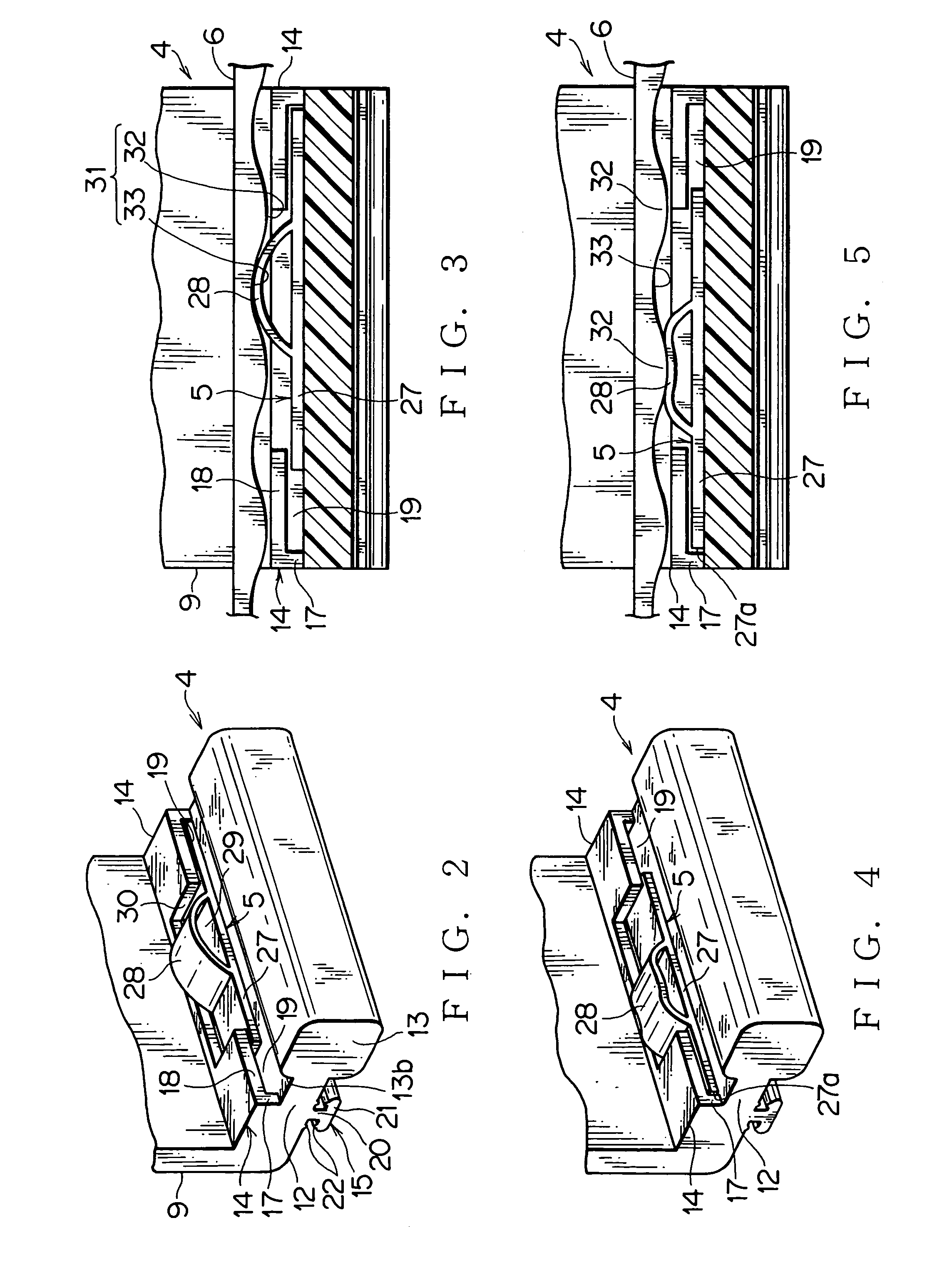
[0037]A first embodiment of a power-supply device 1 according to the present invention will be described below with reference to FIGS. 1 to 6.

[0038]The power-supply device 1 is applicable to a sliding door, a sliding seat, or a rotary back door of a vehicle and the like. The power-supply device 1 includes: a synthetic resin made case 2; a guide rail 3 mounted on the case; a slider 4 slidably engageable with the guide rail 3; an urging member 5 mounted on the slider 4; and a long rack 6 for slidably engaging with the urging member 5.

[0039]The case 2 is composed of a wide part 2a, and a narrow part 2b extended integrally with the wide part 2a in a longitudinal direction. The case includes a step wall 7 having an opening 8 disposed between the wide part 2a and the narrow part 2b, and a slit 10 through which a projection 9 is projected from the slider 4 and slid forward and backward within a substantially total length of the case 2. The case 2 is enclosed with walls except the opening 8...

second embodiment

[0059]A second embodiment of a power-supply device 1 according to the present invention will be described below with reference to FIGS. 7 to 9.

[0060]As shown in FIGS. 7 to 9, the rack 6 of the power-supply device 1′ is disposed between the guide rail 3 of the case 2. Accordingly, the urging member 5 is disposed on the opposite side of the slider 4′ from that of the first embodiment. Identical reference numbers will designate identical elements and only the difference existing in comparison with the first embodiment will be explained.

[0061]As shown in FIG. 6, the slidable engaging part 15 of the slider 4′ is slidably engaged through the slit 24 with the guide rail 3 having the substantially rectangular section. As shown in FIGS. 7 to 9, the resilient part 28 of the urging member 5 of the slidable engaging part 15 is resiliently and slidably engaged with the rack 6 inside the guide rail 3.

[0062]The slidable engaging part 15 of the second embodiment integrally includes the pair of guid...


PUM


Abstract

There is provided a power-supply device includes: a case receiving a curved wire harness; a guide rail mounted on the case; a slider mounted slidably on the guide rail, through which the wire harness being routed out from the case; an urging member having a resilient part mounted on the slider, and a long rack. The long rack alternately has crests and troughs, and slidably engaged with the resilient part of the urging member. Preferably, the long rack is mounted on the guide rail, and the urging member is mounted on a slidable engaging part of the slider for engaging with the guide rail. Preferably, the urging member is slidably engaged with the slider.

Description

CROSS REFERENCE TO RELATED APPLICATIONS[0001]This application is based on Japanese Patent Application No. 2005-058484 filed in Japan Patent Office on Mar. 3, 2005, the contents of which are hereby incorporated by reference.BACKGROUND OF THE INVENTION[0002]1. Field of the Invention[0003]The present invention relates to a power-supply device for constantly feeding electric power to a sliding door, a sliding seat of a vehicle or the like by a substantially U-shaped wire harness expanded and contracted with a movement of a slider in a case.[0004]2. Description of the Related Art[0005]FIG. 10 shows an embodiment of a conventional power-supply device 61 disclosed in FIG. 2 of Japanese Published Patent Document H11-342807.[0006]This power-supply device 61 is used for a sliding door of a vehicle, and includes: a long case 63 for receiving a substantially U-shaped flat wire harness 62; a resilient reinforcing plate 64 mounted on an outer wall of the wire harness 62; a slider 65 disposed on a...

Claims


Application Information

Patent Timeline
Patent Type & Authority Patents(United States)
IPC IPC(8): H01R33/00
CPCB60R16/0215H02G11/00H02G11/006B60R16/027
Inventor TSUBAKI, AKIRA
Owner YAZAKI CORP
Learn More