Magnetic tape measure end hook

a technology of end hooks and magnetic tapes, applied in the field of magnetic tape measures, can solve the problems of end hook configuration, none have proved entirely satisfactory, and the end hook is difficult to keep in the desired location

Inactive Publication Date: 2007-07-10
COOPER BRANDS
View PDF92 Cites 43 Cited by
  • Summary
  • Abstract
  • Description
  • Claims
  • Application Information

AI Technical Summary

Problems solved by technology

However, it is sometimes difficult to keep the end hook in the desired location.
While a number of magnetic end hook configurations have been proposed, none have proven entirely satisfactory.

Method used


Image

  • Magnetic tape measure end hook
  • Magnetic tape measure end hook
  • Magnetic tape measure end hook

Examples


Embodiment Construction

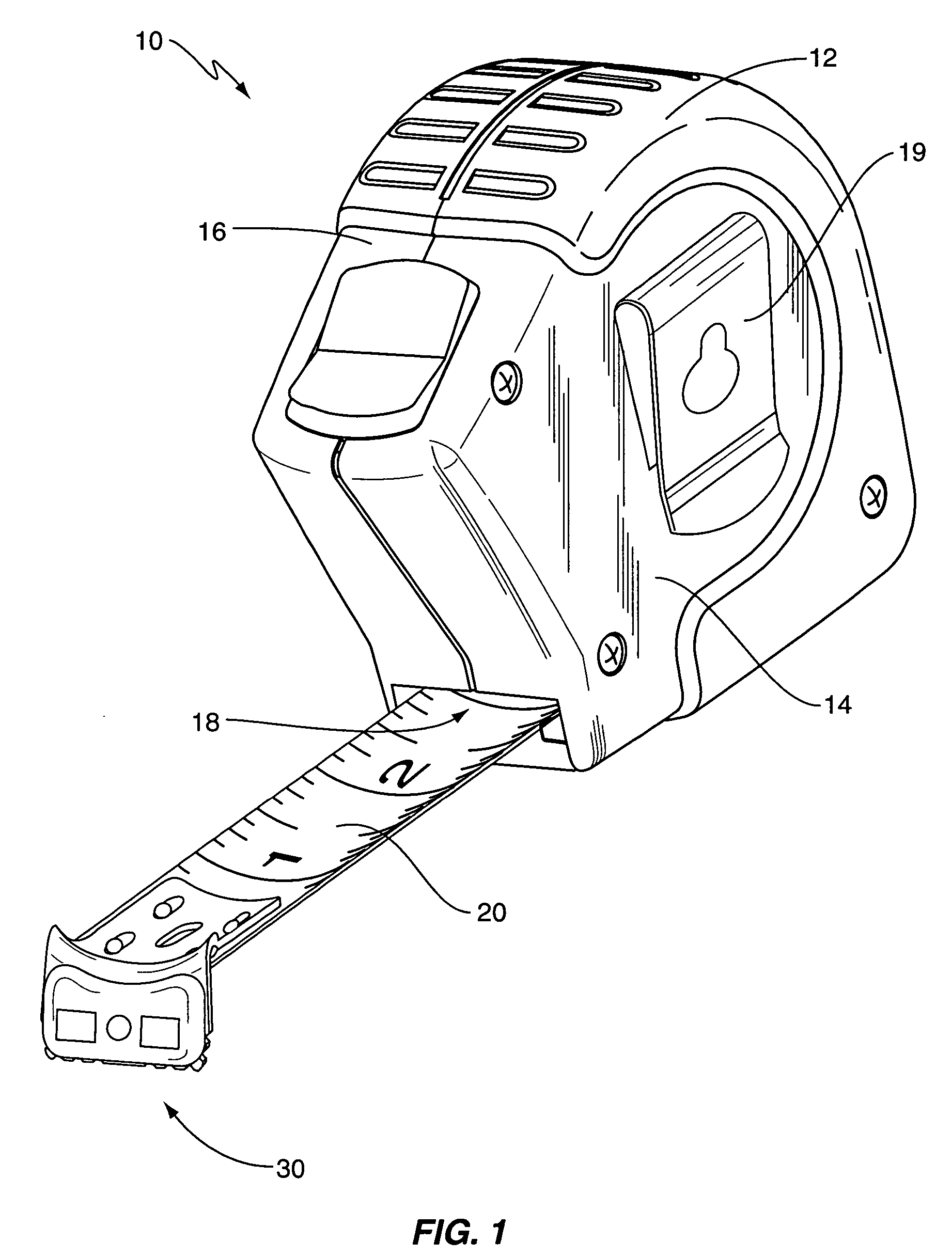
[0010]As illustrated in FIG. 1, a tape measure, generally designated 10, is shown constructed according to one embodiment of the present invention. The tape measure 10 includes a housing 12, a coilable measuring tape or blade 20, and an end hook assembly 30. The housing 12 typically has a generally squarish shape, with a rounded upper-rear corner, and may have a slightly projecting nose. The housing 12 includes an opposing pair of sidewalls 14 and an interconnecting peripheral wall 16 which help define an internal chamber (not shown) that houses the coiled portion of the tape 20, a suitable tape-biasing device (e.g., retraction spring), and portions of the blade locking mechanism. The housing 12 typically includes an opening 18 near its lower-front corner that connects to the internal chamber. The distal end of the tape 20 extends through this opening 18 for selective deployment therefrom. The housing 12 is preferably sized to fit within a user's hand and / or conveniently stored on a...


PUM


Abstract

A magnetic end hook for a tape measure has a hook member having a mounting section extending in a first direction and a hooking section extending away from the mounting section in a second direction generally transverse to the first direction. A distinct bezel affixes to the hooking section so as to capture a magnet between the bezel and the hooking section. A magnet is disposed at least partially in a hole in the hooking section and a hole in the bezel so as to be visible from both front and rear views of the end hook. The magnet may include flanges and a fastener, such as a rivet, may secure the bezel in place. There may be a second magnet similarly situated. A tape measure and methods of assembly are also described.

Description

BACKGROUND OF THE INVENTION[0001]The present invention is directed generally to tape measures of the type commonly used to measure linear distances.[0002]Modern tape measures (or “tape rules”) typically include an L-shaped metallic end hook for hooking onto measurement surfaces. Such end hooks, while being available in a wide variety of shapes and sizes, all basically operate by being either pressed against a surface for an abutting-type measurement, or hooked over a suitable edge for a hooking-type measurement. However, it is sometimes difficult to keep the end hook in the desired location. As such, various approaches have been proposed to provide alternative means for helping keep the end hook in the desired location. One area receiving attention is the addition of magnets to the end hook so that the end hook may be at least partially magnetically coupled to metallic measurement surfaces (e.g., metal wall studs). While a number of magnetic end hook configurations have been propose...

Claims


Application Information

Patent Timeline
Patent Type & Authority Patents(United States)
IPC IPC(8): G01B3/10
CPCG01B3/1056G01B2003/1028Y10S33/01G01B3/10
Inventor CRITELLI, JAMES M.LIN, LIN PING
Owner COOPER BRANDS
Why Eureka
Try Eureka