Effector affixing device

a technology of effector and affixing device, which is applied in the direction of electrophonic musical instruments, lighting and heating apparatus, instruments, etc., can solve the problems of difficult replacement of effector, difficult operation of effector, and difficult disassembly and installation of effectors, so as to facilitate the replacement of effectors. , the effect of easy installation height and easy operation

Inactive Publication Date: 2013-09-17
MIZUHO GOUSEI INDSHO CO LTD
View PDF8 Cites 13 Cited by
  • Summary
  • Abstract
  • Description
  • Claims
  • Application Information

AI Technical Summary

Benefits of technology

[0026]According to the first invention, the replacement of the effector can be facilitated. Further, the effector installation height can be easily changed. Since the shield lines and others can be accommodated in the separation space below the effector affixing base, and hence the wiring lines, e.g., the shield lines do not interfere with the switching operation using a toe. Even in case of arranging the effectors in two rows in the front-rear direction, since the rear effector can be placed at a higher position, the switch of the front effector is not operated by mistake at a time of operating the wah pedal switch of the rear effector.
[0027]According to the second invention, the positional change or the replacement of the effector can be easily carried out in accordance with a request of the performer or a situation in the concert hall, and the effector operation can be also facilitated.
[0028]According to the third invention, even if each effector has a different bottom surface dimension, the effector affixing device associated with this dimension can be provided. Furthermore, even if the effector has a trapezoidal bottom surface shape, it is possible to cope with this shape by changing the lengths of the position adjustment rails.
[0029]According to the fourth invention, even in case of replacing to the effector having a bottom surface dimension slightly different from a bottom surface dimension of the effector affixing portion formed of each corner member, the effector can be affixed without backlash of the effector affixing base, and the replacement of the effector can be facilitated.
[0030]According to the fifth invention, the effector and the effector affixing base can be readily affixed or taken off.
[0031]According to the sixth invention, since the performance operation can be carried out so as to tilt the effector as the performer desires, the operation of the wah switch can be further facilitated.

Problems solved by technology

In such a case, since it is not easy to change to sound quality desired by the performer in the multi-effector in which an acoustic state is preset, there are many performers who rearrange and adjust the order of a plurality of continuous single-function effectors and control the acoustic effects at a time of performance.
However, in a situation adopting the technology disclosed in Patent Document 1, holding force of the pushing claws is weakened as the base is repeatedly used, an accident that the effector is kicked and comes off at a time of switching using a toe or a shield line catches a toe to remove the effector is apt to occur, an operation of the effector is not easy, and a switching operation may be possibly erroneously performed to disable performance.
Furthermore, at a time of replacing the effector, the shield line must be accommodated so that it does not obstruct performance when a pedal switch is operated, and there is a problem that replacement of the effector is not easy.
However, there is a problem that, on a dark stage or a stage in a lighting environment subjected to a dark change by lights-out, selecting a predetermined effector is difficult and an effector operation is not easy.

Method used


Image

  • Effector affixing device
  • Effector affixing device
  • Effector affixing device

Examples


embodiment 1

(Embodiment 1)

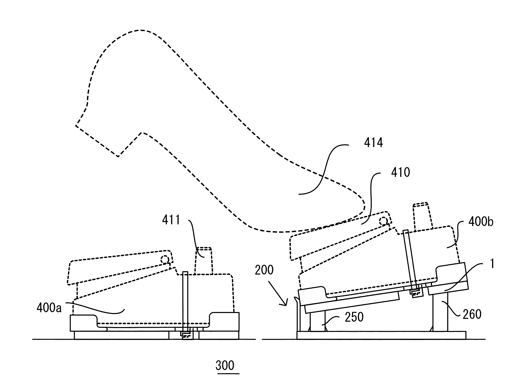
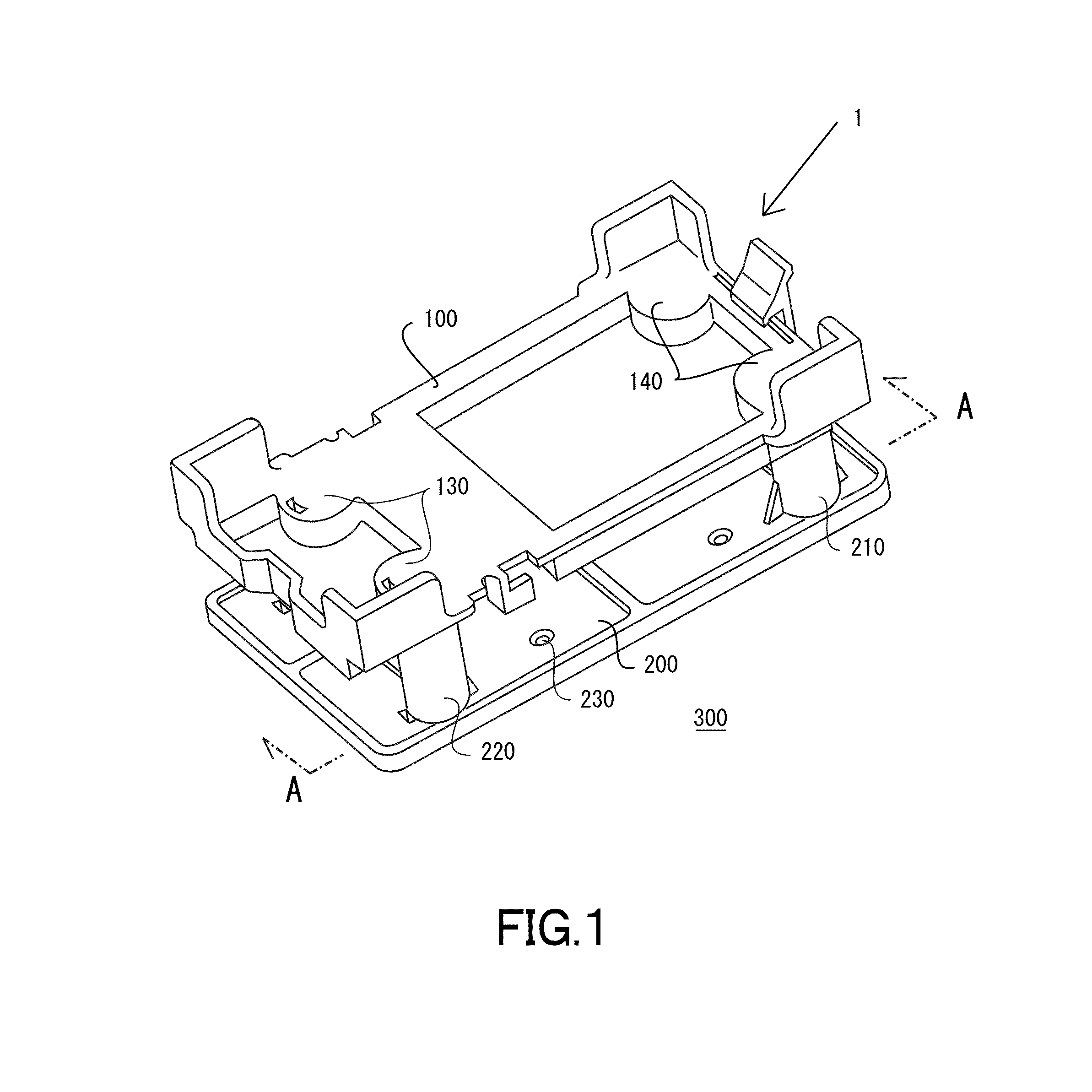
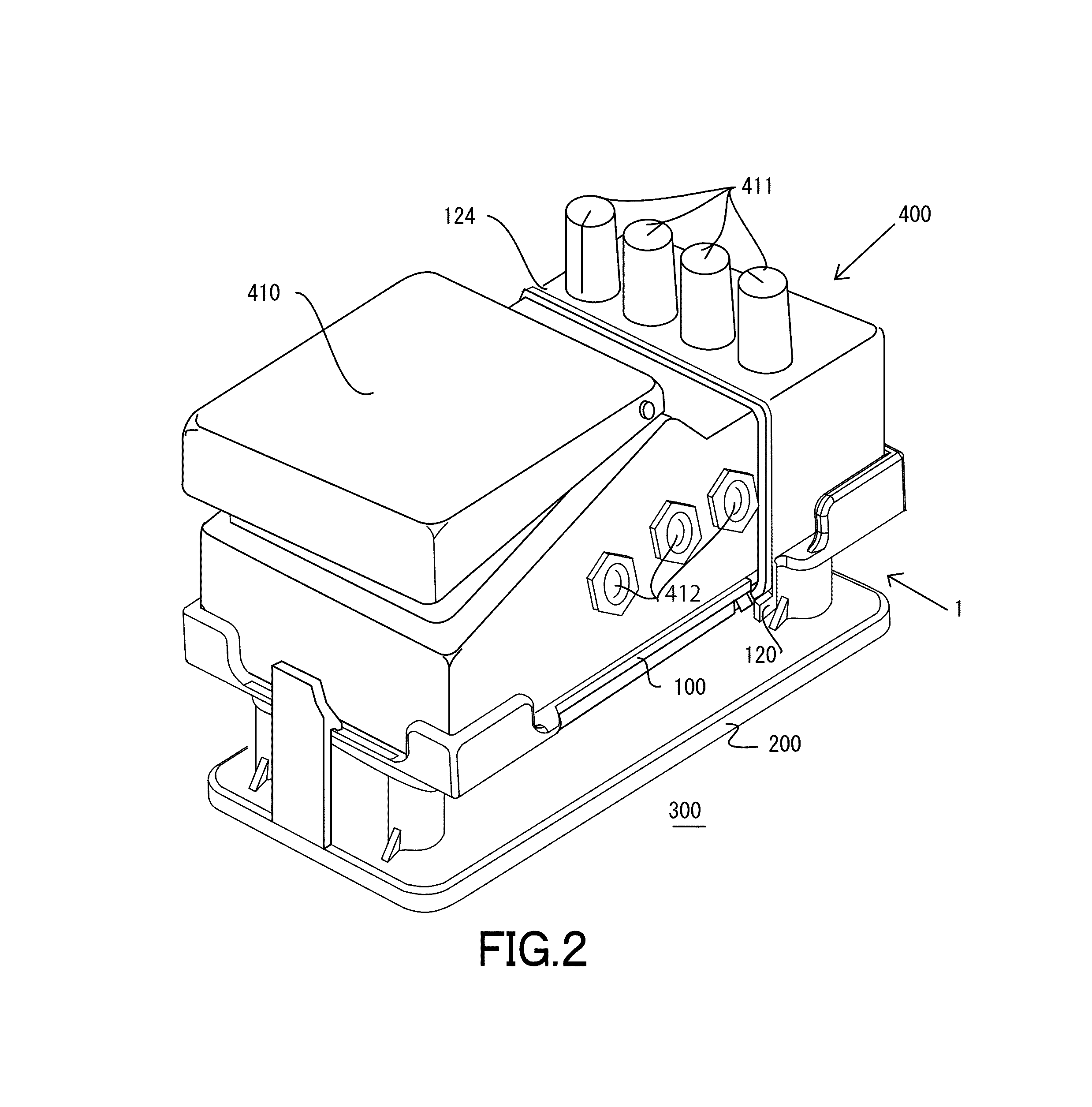
[0054]Embodiment 1 according to the present invention will now be described hereinafter with reference to FIG. 1 to FIG. 7. FIG. 1 is a perspective view of an effector affixing device, FIG. 2 is a perspective view of the effector affixing device in a state that an effector comprising a wah pedal is affixed, FIG. 3 is an explanatory view of a state that the effector is arranged on an effector board, FIG. 4 is a perspective view of an effector affixing base, FIG. 5 is a perspective view of a separation member, FIG. 6 is an explanatory view of a state that a decorative string is disposed to protrusions, and FIG. 7 is cross-sectional views taken along a position A-A in FIG. 1.

[0055]An outline of a configuration of an effector affixing device will now be described with reference to FIG. 1. In an effector affixing device 1 according to Embodiment 1, supports 210 and 220 formed on a separation member 200 are fitted in and coupled with depressed portions 130 and 140 formed in ...

embodiment 2

(Embodiment 2)

[0073]Embodiment 2 will now be described with reference to FIG. 8. In Embodiment 2, on the front side of the separation member 200 according to Embodiment 1, a front tongue portion 270 is extended so as to be concave upward, and a lighting device that causes reflection on the front tongue portion 270 and illuminates a front face of an effector 400 is provided. The lighting device is formed integrally with a light-emitting diode 510 and a power supply mechanism 500 which includes a power supply and a switch. The lighting device is disposed in a separation space between an effector affixing base 100 and the separation member 200 with a light-emitting side of the lighting-emitting diode 510 being provided on the front tongue portion 270 side. Further, light emitted from the light-emitting diode 510 is reflected on the front tongue portion 270 and applied to front faces 413 of an effector housing and a wah pedal. As a result, even if stage illumination is put out and a sta...

embodiment 3

(Embodiment 3)

[0075]Embodiment 3 will now be described with reference to FIG. 9. In regard to a separation member 200 according to Embodiment 3, front and rear supports 250 and 260 have different heights. In Embodiment 3, configurations of the front and rear supports are the same except that these supports have different heights from those of the supports according to Embodiment 1, a configuration of an effector affixing base is the same as that according to Embodiment 1, and hence a description thereof will be omitted. It is possible to select the front or rear supports as a target of increase in height in accordance with a performer's request.

[0076]Moreover, a height of a separation space between the effector affixing base 100 on the support side with a small height arranged on the front or rear side and a separation member 200 is a height that enables shield lines to intersect with each other, and the height of the lower supports on the front side is set to 20 mm in Embodiment 3....


PUM


Abstract

An effector affixing device affixes an acoustic effector on a plate material. The effector affixing device includes an effector affixing base and a separation member. The effector affixing base is provided with an effector affixing component. The separation member includes supports erected below the vicinities of four corners of the effector affixing base. The effector affixing base and the separation member are separably coupled with each other. The effector affixing base includes a bottom plate and an effector holding piece. The bottom plate supports the effector. The effector holding piece is erected from an edge portion of the bottom plate. The effector affixing device includes a separation space having a height that at least allows shield lines to intersect with each other below the bottom plate in a state that the effector affixing base is coupled with upper portions of the supports.

Description

TECHNICAL FIELD[0001]The present invention relates to an effector affixing device that facilitates an operation of an acoustic effector. In more detail, the present invention relates to an effector affixing device that facilitates replacement of an effector, prevents a shield line and others protruding from the effector from obstructing a switching operation, and avoids failures in operation of the effector.BACKGROUND ART[0002]There is a musical instrument such as an electric guitar that is played in an arbitrary volume by changing sound generated by a sound source into an electrical signal. In an electric guitar or the like, a musical instrument itself and an amplifier are subjected to sound quality adjustment through an acoustic effector that produces various acoustic effects. As the effector, there are a single-function effector and a multi-effector having a plurality of effect functions implemented as one. In the multi-effector, a plurality of types of acoustic effects are store...

Claims


Application Information

Patent Timeline
Patent Type & Authority Patents(United States)
IPC IPC(8): G10H1/32
CPCF16M13/005G10H1/348F21V7/0008
Inventor GOTO, TOSHIHIRO
Owner MIZUHO GOUSEI INDSHO CO LTD
Why Eureka
Try Eureka