Row divider having a variable-height ear saver

a row divider and variable-height technology, applied in the field of header row dividers, can solve the problems of compromising the performance of the ear saver for the other condition, maximizing the height of the ear saver for one condition, and wasting resources on replacement ear savers

Inactive Publication Date: 2007-07-10
DEERE & CO
View PDF14 Cites 32 Cited by
  • Summary
  • Abstract
  • Description
  • Claims
  • Application Information

AI Technical Summary

Problems solved by technology

However, in down corn conditions, a relatively tall ear saver creates a slope on the row divider that is too steep for the crop to easily slide over and into the row units.
For an ear saver that is a permanent, non-removable design feature of the row divider, maximizing ear saver height for one condition compromises ear saver performance for the other condition.
Alternatively, removable ear savers often get lost, may come off in the machine and cause damage, and are time consuming to install and remove with changing crop conditions.

Method used


Image

  • Row divider having a variable-height ear saver
  • Row divider having a variable-height ear saver
  • Row divider having a variable-height ear saver

Examples


Embodiment Construction

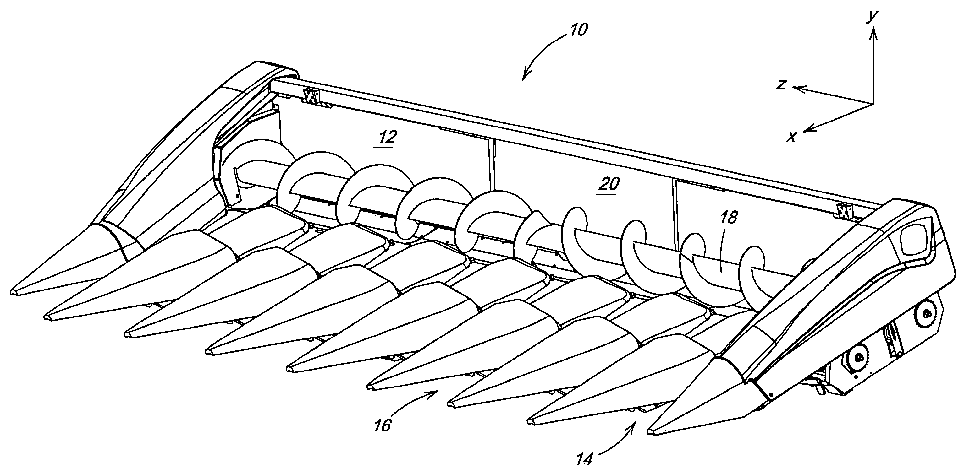
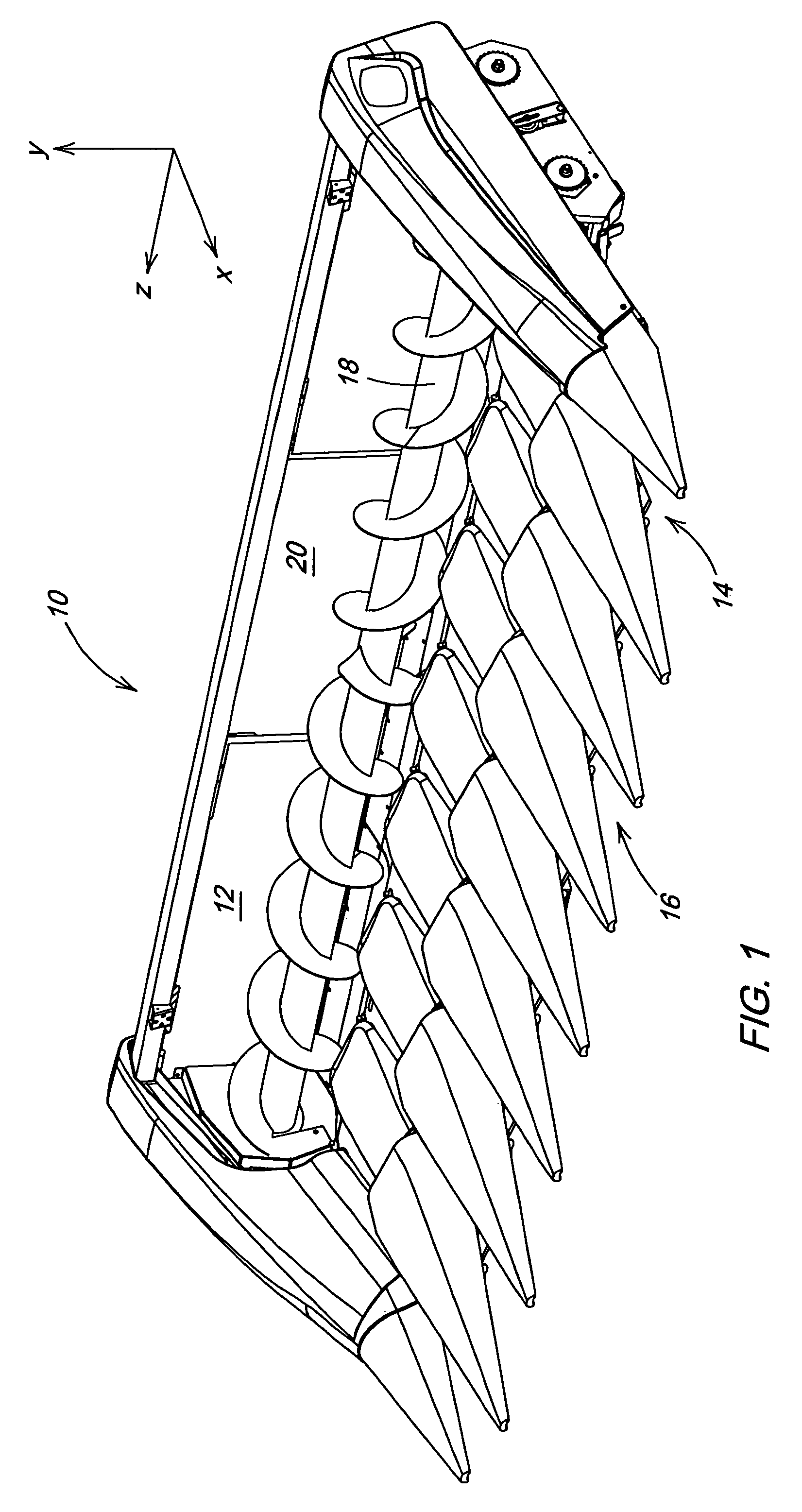
[0013]FIG. 1 shows a perspective view of a corn header with reference to coordinate axes X, Y, and Z. In this following detailed description, the X-axis defines horizontal longitudinal, with the positive X direction defining forward. The Y-axis defines vertical, with the positive Y direction defining up. The Z-axis defines horizontal lateral, with the positive Z direction defining right.

[0014]The corn header 10 in the illustrated embodiment is comprised of a frame 12, several row units 14 distributed along the frame 12, a row divider 16 positioned between each row unit 14, a conveying auger 18 behind the row units 14, and an opening 20 at the center of the header 10 leading into the combine. Referring to FIG. 1, the frame 12 extends laterally across the entire width of the header 10 and functions to support the header structure. The row units 14 extend longitudinally forward from the frame 12 and function to cut and gather standing rows of corn. The row dividers 16 mount above the r...


PUM


Abstract

For a row crop header, a row divider having a variable-height ear saver feature. The row divider comprises a point, a cover, and a partition. The point has a trailing edge vertically moveable relative to the cover. The partition fills a resultant gap between the point and the cover, forming a variable-height ear saver feature. A crankshaft functions to articulate the trailing edge relative to the cover, and to move the partition vertically with the trailing edge. A support functions to support the point at a midpoint. A guide constrains the partition within the gap.

Description

FIELD OF THE INVENTION[0001]This invention related to agricultural combine headers, and more specifically, to a header row divider having a variable-height ear savers.BACKGROUND OF THE INVENTION[0002]An agricultural combine is a large machine used to harvest a variety of crops from a field. During a harvesting operation, a header at the front of the combine cuts ripened crop from the field. A feederhouse supporting the header transfers the crop material into the combine. Threshing and separating assemblies within the combine remove grain from the crop material and transfer the clean grain to a grain tank for temporary holding. Crop material other than grain exits from the rear of the combine. An unloading auger transfers the clean grain from the grain tank to a truck or grain cart for transport, or to another receiving bin for holding.[0003]Row crop and corn headers are header types commonly used when harvesting crops planted in rows such as soybeans and corn. These header types hav...

Claims


Application Information

Patent Timeline
Patent Type & Authority Patents(United States)
IPC IPC(8): A01D45/02
CPCA01D45/021
Inventor MOSSMAN, MICHAEL WAYNE
Owner DEERE & CO
Why Eureka
Try Eureka