
Installation structure of brake pedal

a technology of installation structure and brake pedal, which is applied in the direction of mechanical control devices, instruments, tractors, etc., can solve problems such as injury to the driver's legs, and achieve the effect of preventing or minimizing injury to the driver

Inactive Publication Date: 2007-07-10
HYUNDAI MOTOR CO LTD
View PDF8 Cites 10 Cited by
  • Summary
  • Abstract
  • Description
  • Claims
  • Application Information

AI Technical Summary

Benefits of technology

The structure effectively prevents injury to the driver by automatically releasing the brake pedal during a collision, redirecting the impact force away from the driver and maintaining stability under normal conditions.

Problems solved by technology

In the event of a vehicle collision, the displacement of the master cylinder and booster disposed in the engine compartment can force the brake pedal to be pushed toward the driver, causing injury to the driver's legs.

Method used


Image

  • Installation structure of brake pedal
  • Installation structure of brake pedal
  • Installation structure of brake pedal

Examples


Embodiment Construction

[0014]The preferred embodiment of the present invention will now be described in detail with reference to the attached drawings.

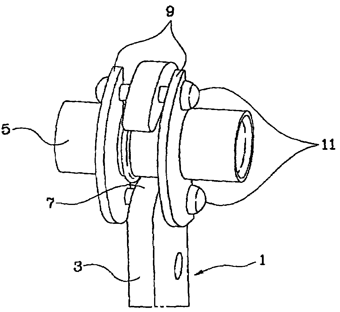
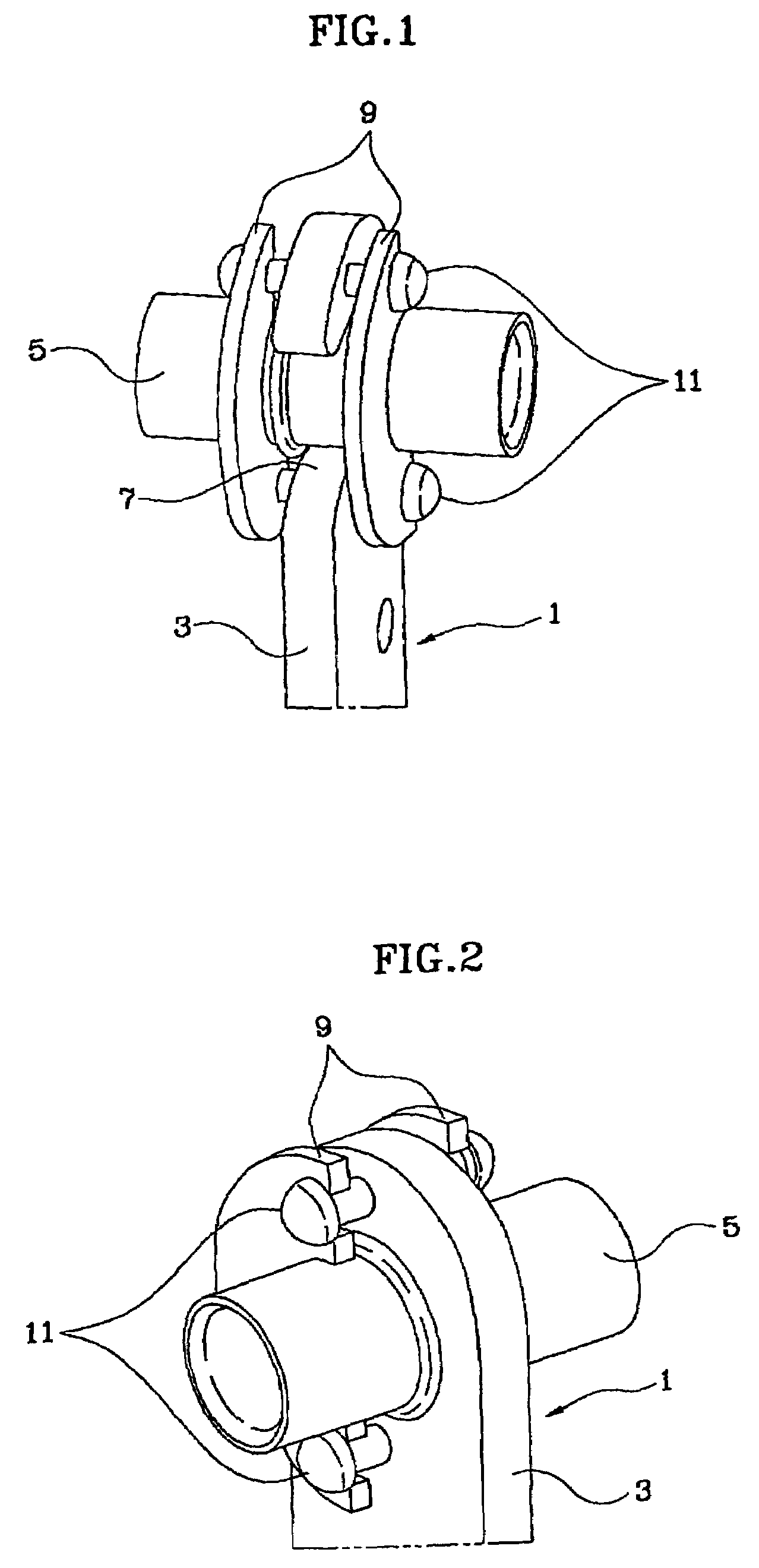
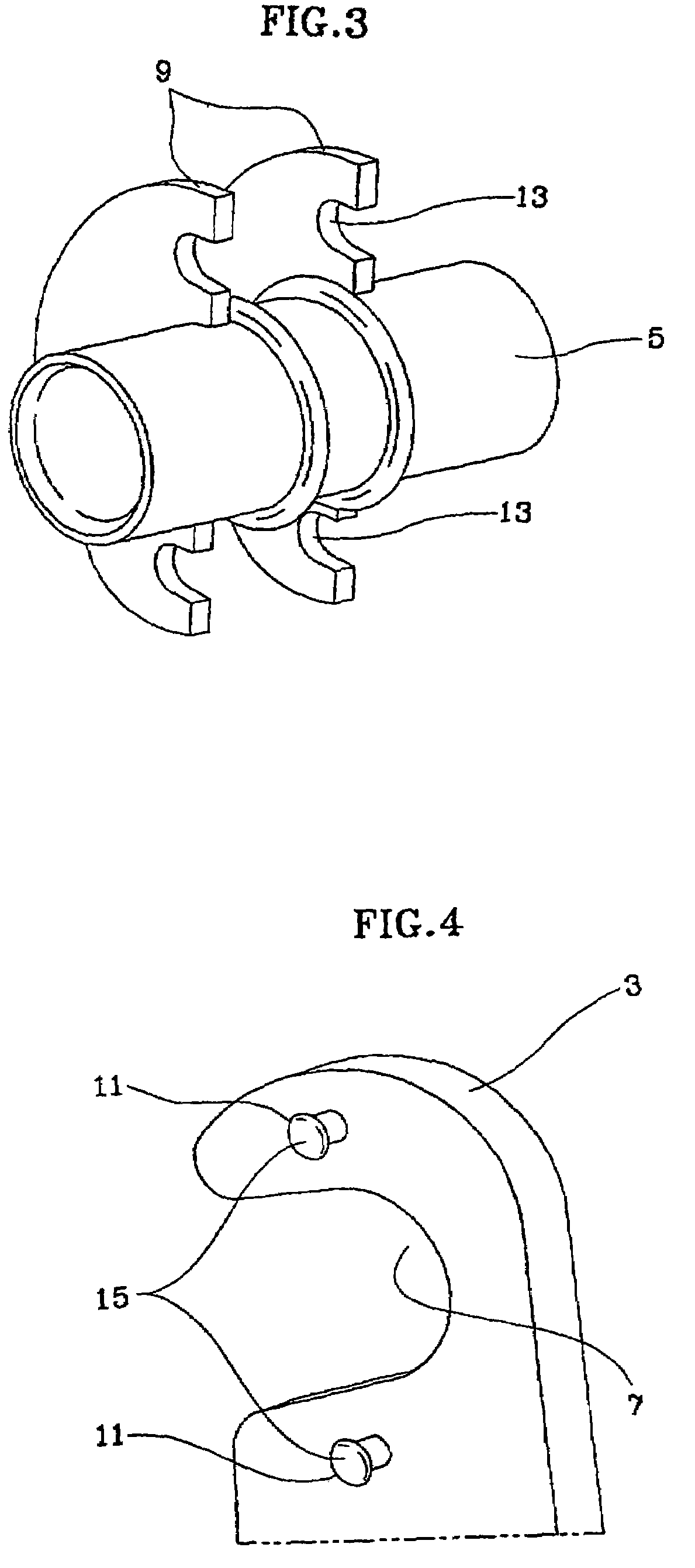
[0015]Referring to FIGS. 1 and 2, a pedal arm 3 of a brake pedal 1 is pivotally coupled to a hinge pipe 5. With reference to FIG. 5, a hinge groove 7 of the pedal arm 3 couples with the hinge pipe 5 and a portion of the hinge groove 7 opened towards the front of the vehicle has a smaller width than that of the outer diameter of the hinge pipe 5. By way of reference, FIG. 5 describes only the hinge pipe 5 and the pedal arm 3 and omits illustrations of other components.

[0016]Once the hinge groove 7 of the pedal arm 3 is forcibly coupled with the hinge pipe 5, the pedal arm 3 is designed not to be separated by itself from the hinge pipe 5. However, when a vehicle accident occurs, the displacement of the master cylinder and booster forces the brake pedal 1 to be pushed toward the driver, and the hinge groove 7 of the pedal arm 3 is separated from the hinge pipe...


PUM


Abstract

An installation structure releases a brake pedal in a vehicle collision. A pedal arm has a groove coupled with a pipe. A front portion of the groove has a smaller width than the pipe. Alternatively, a pedal arm is hingedly mounted on a support member. A connector secures the pedal arm to the support member for normal operation, and permits separation of the pedal arm from the support member in response to a reward force resulting from a collision impact. The support member has a cylindrical member, and the pedal arm defines a forward facing opening, force-fit onto the cylindrical member. The opening has a width smaller than the cylindrical member. Alternatively, the connector has two support plates on a pipe of the cylindrical member, at both sides of the pedal arm. The plates have rear-facing grooves, and coupling members protruding from the pedal arm are received in the grooves.

Description

CROSS-REFERENCE TO RELATED APPLICATIONS[0001]This application claims priority of Korean Application No. 10-2003-0071000, filed on Oct. 13, 2003, the disclosure of which is incorporated fully herein by reference.FIELD OF THE INVENTION[0002]The present invention relates to an installation structure of a brake pedal incorporated in a vehicle. More particularly, the present invention relates to a pedal installation structure adapted to prevent injury to the lower parts of a driver due to a brake pedal, which pivotally thrusts toward the driver during a vehicle collision.BACKGROUND OF THE INVENTION[0003]In the event of a vehicle collision, the displacement of the master cylinder and booster disposed in the engine compartment can force the brake pedal to be pushed toward the driver, causing injury to the driver's legs.SUMMARY OF THE INVENTION[0004]Embodiments of the present invention provide an installation structure for a brake pedal adapted to automatically release a fixed state of the ...

Claims


Application Information

Patent Timeline
Patent Type & Authority Patents(United States)
IPC IPC(8): G05G1/30B60D1/28B60K28/10B60T7/06B60R21/09G05G1/327
CPCG05G1/30G05G1/327G05G1/60Y10T74/20888Y10T74/20528B60T7/06
Inventor LEE, CHANG-HYUN
Owner HYUNDAI MOTOR CO LTD
Learn More