
Parabolic trough collector

a collector and parabolic technology, applied in the field of parabolic trough collectors, can solve the problems of high optical loss in the flexible union area of the flexible union between glass and the absorber tube, inability to absorb concentrated solar radiation by an active absorber tube surface, and high optical loss in the flexible union area of the commercial solar parabolic trough collector for high temperature, etc., to achieve more efficient optical behavior

Active Publication Date: 2007-07-10
SCHOTT AG
View PDF21 Cites 36 Cited by
  • Summary
  • Abstract
  • Description
  • Claims
  • Application Information

AI Technical Summary

Benefits of technology

The present invention is about a parabolic trough collector that has a more efficient optical behavior in the non-active areas. A covering mirror collar with a conic form is installed around the non-active areas to reflect the solar radiation from the non-active absorber part to the active absorber part. The conic form means that the diameter of the mirror collar is coming smaller in direction to the active absorber area. The mirror collar can be formed by two joined conic mirror surfaces orientated in opposite directions. The technical effect of this invention is to improve the optical performance of the parabolic trough collector and increase the efficiency of solar energy conversion.

Problems solved by technology

Commercial parabolic trough collectors for high temperature show high optical losses in the flexible unions between glass and absorber tubes.
Therefore, the absorption of the concentrated solar radiation by an active absorber tube surface is not possible in those areas.
Commercial solar parabolic trough collectors for high temperature have high optical losses in the flexible union area.
Because of the necessity of flexible bellows and the space for the absorber tube supports those areas cannot be used as active absorber area.
The use of the concentrated radiation onto those non-active areas seems very complicated because of the continuously changing sun incident angle.

Method used


Image

  • Parabolic trough collector
  • Parabolic trough collector
  • Parabolic trough collector

Examples


Embodiment Construction

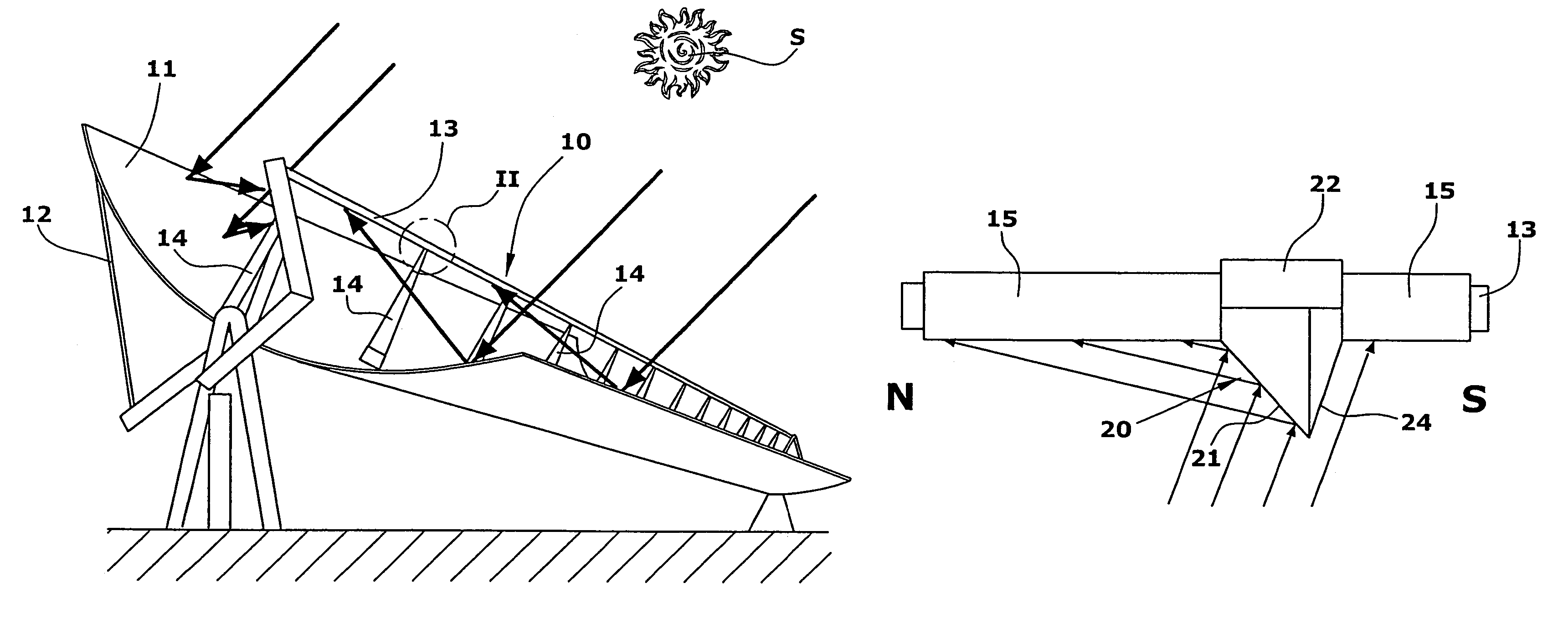
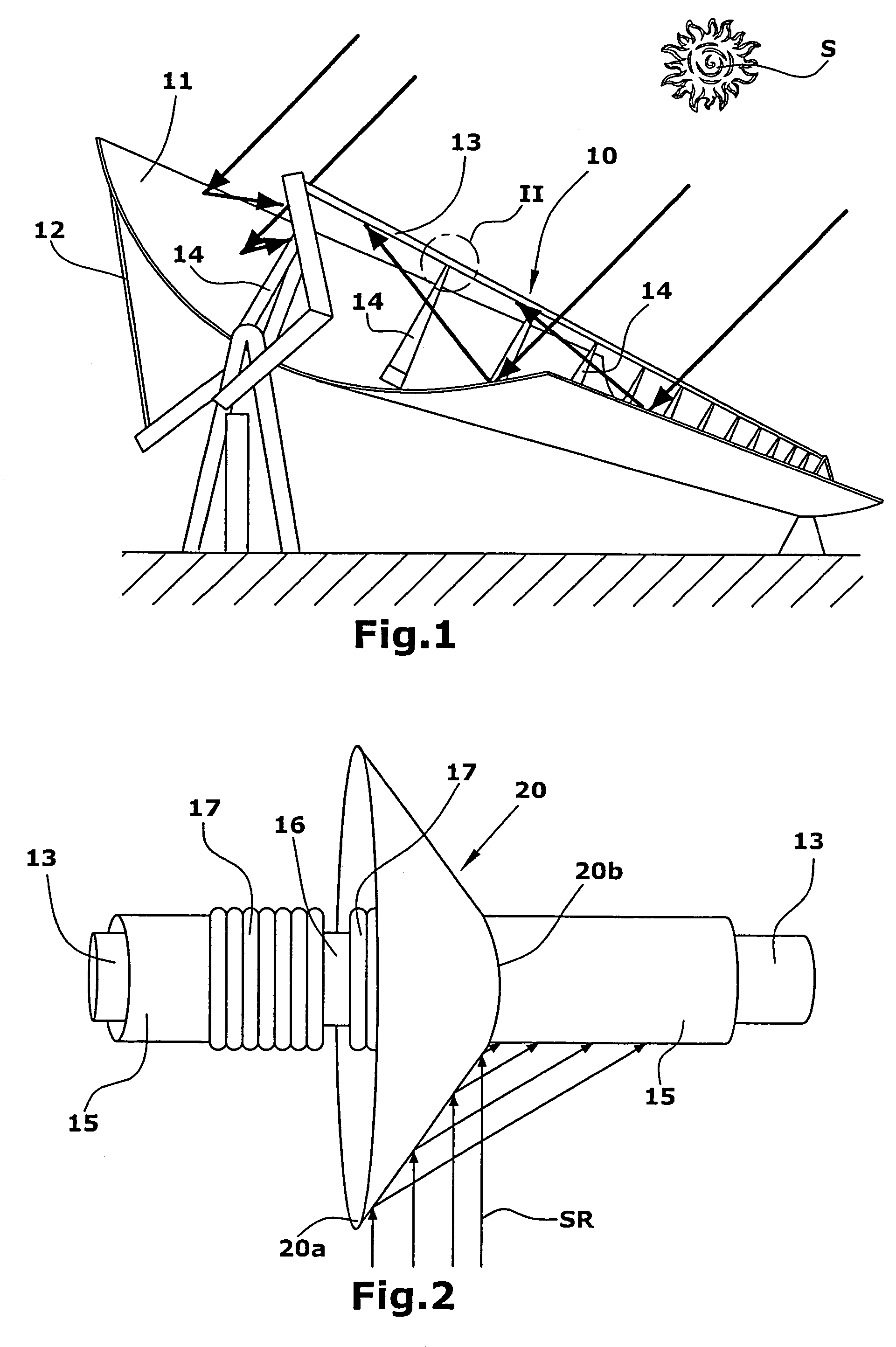
[0023]A parabolic trough collector (10) with a parabolic reflector (11) is represented in FIG. 1. El parabolic reflector (11) is installed on a reflector support (12). Along the focus line of the parabolic reflector (11) the receiver formed by single absorber tubes (13) is installed on absorber supports (14) that are fixed with the reflector structure. The reflector (11), the reflector support (12), the single absorber tubes (13) and the absorber supports (14) form a fixed unit that can be turned around the collector tracking axis in order to follow the sun S. The parallel incident radiation coming from the sun S is focused by the parabolic reflector (11) onto the absorber tubes (13). The heat transfer fluid, for example thermal oil or water, flows through the absorber tubes (13) and is heated up. In the collector outlet another collector can be connected in order to go ahead with the heating or the heat transfer fluid can be pumped to a power block in order to produce electrical en...


PUM


Abstract

The parabolic trough collector has a receiver formed by several single absorber tubes (13). The single absorber tubes (13) are supported by absorber tube supports (14) and surrounded by a glass tube (15). Because of different expansion behavior of the absorber tube (13) and the glass tube (15) during collector operation flexible unions (17) are foreseen between absorber tube (13) and glass tube (15). In order to use the radiation coming to the non active-area where the absorber tube supports (14) and the flexible unions (17) are installed a mirror collar (20) is installed on this area. The mirror collar (20) is able to reflect the solar radiation, which is coming from different directions, to the active absorber part of the single absorber tubes (13) also when the sun incident angle is changing.

Description

CROSS-REFERENCE TO RELATED APPLICATIONS[0001]This application claims foreign priority of the German patent with the German patent number 103 51 474.0-15STATEMENT REGARDING FEDERALLY SPONSORED RESEARCH OR DEVELOPMENT [0002]D.L.R. (Deutsches Zentrum für Luft-und Raumfahrt), a German federally sponsored Research Organization has declared the invention as “free” for the inventor in case of patent applications in all countries except Germany and Spain.REFERENCE TO SEQUENCE LISTING, A TABLE, OR A COMPUTER PROGRAM LISTING COMPACT DISK APPENDIX[0003]Not applicableBACKGROUND OF THE INVENTION [0004]The invention is related to a parabolic trough collector. The collector has a receiver formed by single absorber tubes that are installed on absorber tube supports and a parabolic reflector that reflects the solar radiation onto the receiver. The single absorber tubes of the receiver are surrounded by glass tubes. Special flexible unions are foreseen to compensate the heat expansion between the st...

Claims


Application Information

Patent Timeline
Patent Type & Authority Patents(United States)
IPC IPC(8): F24J2/24F16L27/12F24S10/40F24S10/70F24S23/00F24S23/70F24S23/71F24S23/74F24S23/75F24S23/79F24S50/20
CPCF24J2/055F24J2/14F24J2/15F24J2/18F24J2/4636Y02E10/44Y02E10/45F24S40/80F24S23/74F24S23/79F24S10/45F24S23/75Y02E10/40
Inventor EICKHOFF, MARTIN
Owner SCHOTT AG
Learn More