Annular one-way valve

a one-way valve, annular technology, applied in the direction of functional valve types, pliable tubular containers, containers, etc., can solve the problems of additional “dripping” flow, valves are relatively complex, and remaining fluid can also contaminate the valv

Inactive Publication Date: 2007-07-17
BRANDES RAYMOND V
View PDF16 Cites 28 Cited by
  • Summary
  • Abstract
  • Description
  • Claims
  • Application Information

AI Technical Summary

Problems solved by technology

Such valves are relatively complex.
They also tend to trap a small amount of fluid in the valve body, which can lead to additional “dripping” flow after the shut off.
The remaining fluid can also contaminate the valve, such as where an air-drying liquid is being fed through the valve.
However, they are subject to contamination by small particles, even one of which can cause the valve to remain open when it should be closed.

Method used


Image

  • Annular one-way valve
  • Annular one-way valve
  • Annular one-way valve

Examples


Embodiment Construction

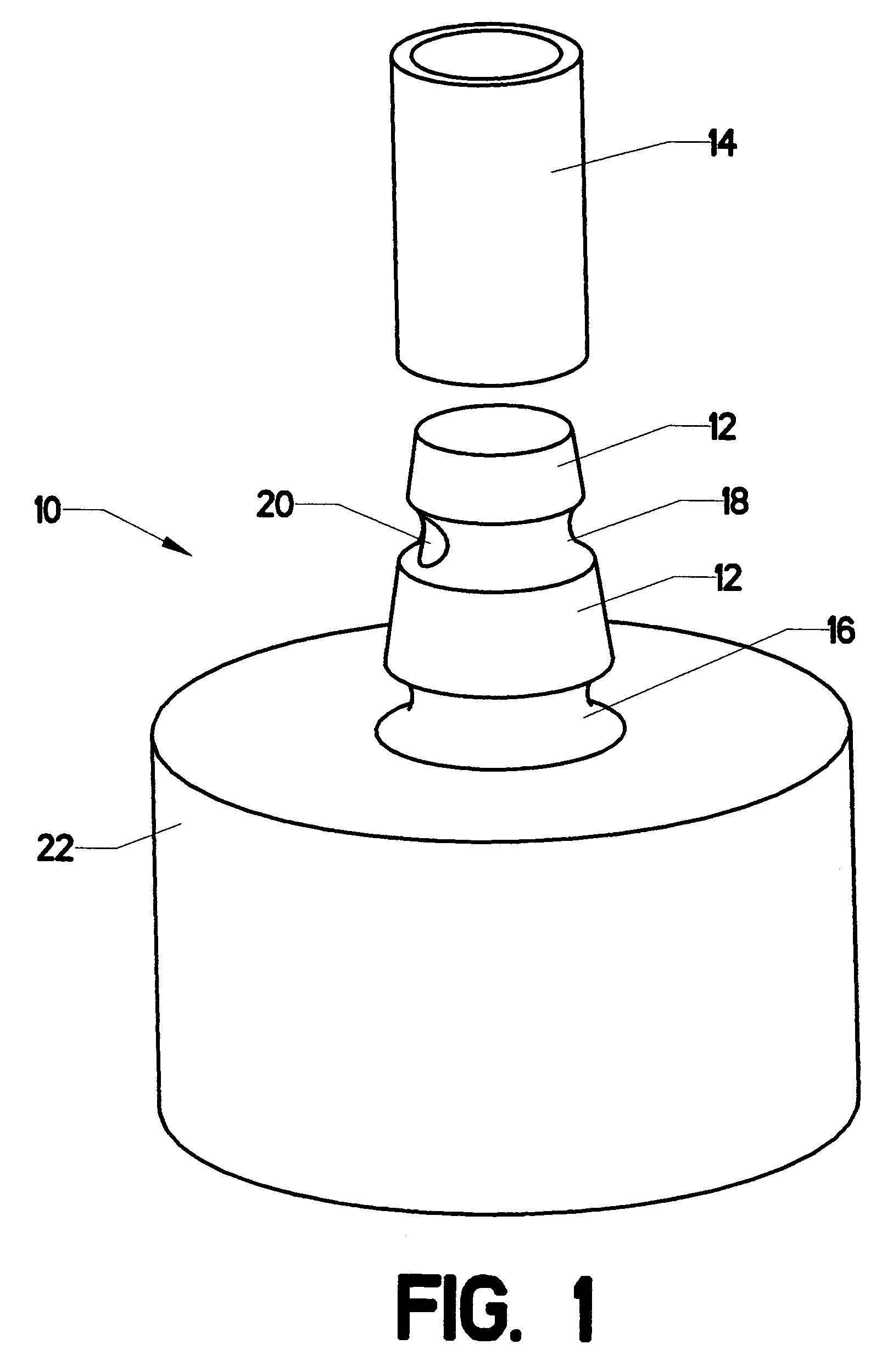
[0017]FIG. 1 shows valve assembly 10 in a disassembled state. Truncated cone 12 has a lower end that is larger then its upper end (where “upper” and “lower” are understood in the context of the orientation shown in the view). Retaining groove 16 is cut into the lower end, while fluid groove 18 is cut into the truncated cone between retaining groove 16 and the upper end of the truncated cone. Connector 22 provides a connection point to a source of fluid which feeds into the valve. Elastic cylinder 14 is hollow. It is made of a pliable material, so that it can be slipped over truncated cone 12, as will be described subsequently.

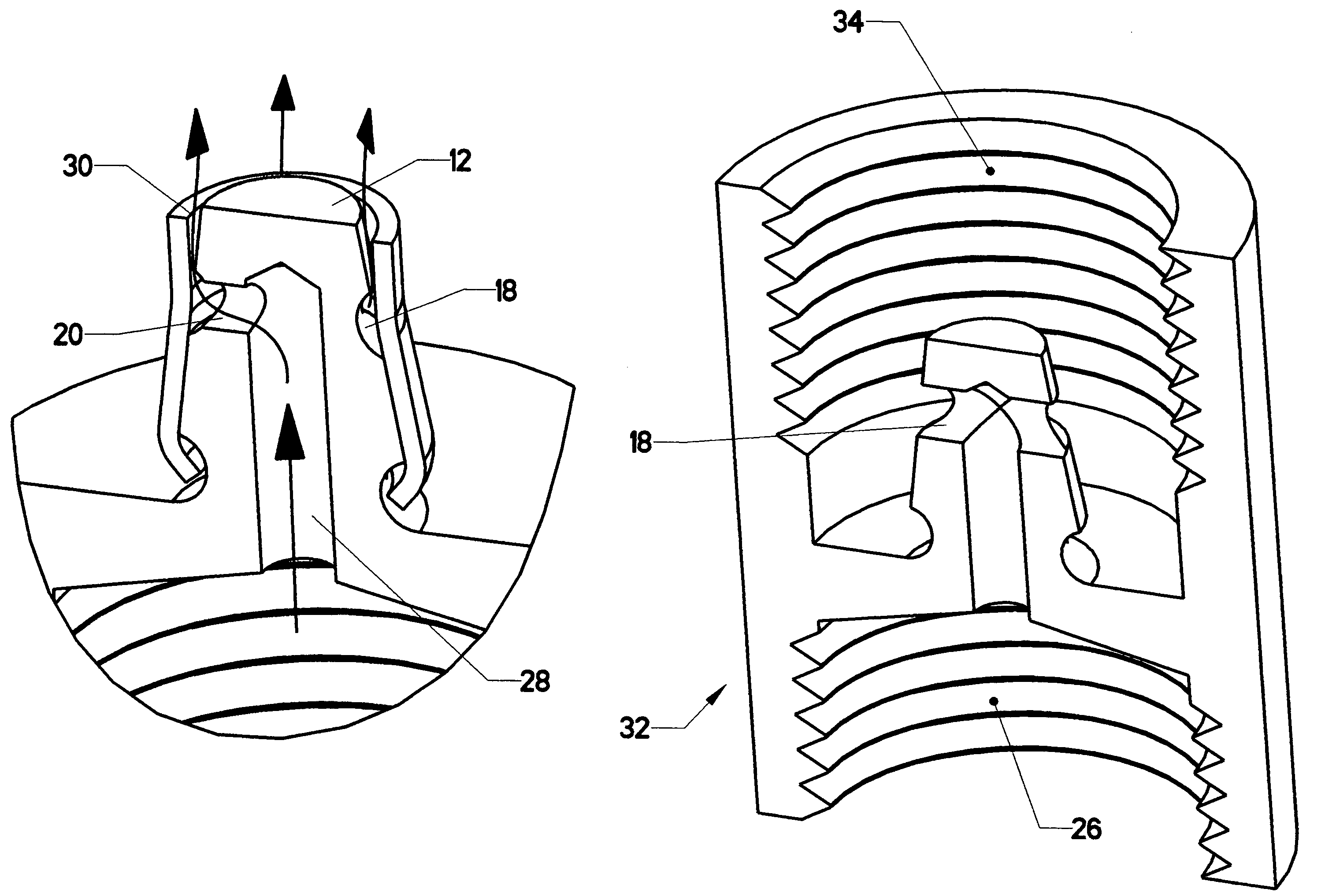
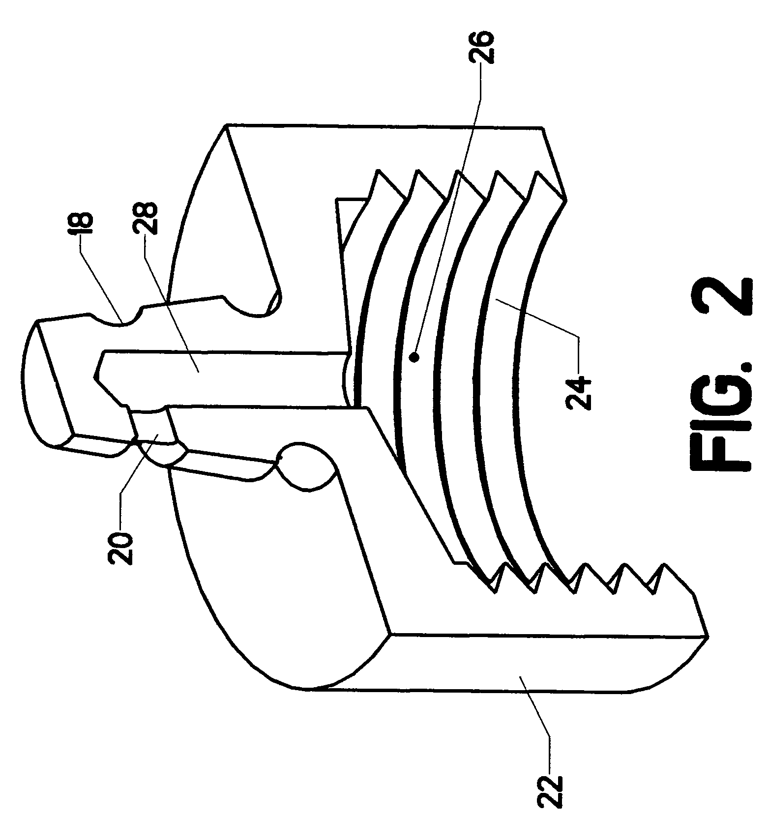
[0018]FIG. 2 is a sectional view through the valve, with elastic cylinder 14 removed. Fluid flows from inside connector 22 through inlet cavity 26, fluid manifold 28, and conduit20. Conduit 20 connects fluid manifold 28 to fluid groove 18.

[0019]FIG. 3 shows a view of valve assembly 10 in an assembled state. Elastic cylinder 14 has been placed over truncated con...


PUM


Abstract

A one-way valve with an annular nozzle. The valve body is a truncated cone with an interior fluid manifold. The truncated cone section includes a lower retaining groove and a fluid groove. A fluid conduit connects the interior fluid manifold to the fluid groove. An elastic cylinder having an internal diameter which is smaller than the truncated cone is slipped over the truncated cone. The lower portion of the elastic cylinder slips into the retaining groove. The upper portion rests over the fluid groove. When fluid pressure within the interior fluid manifold exceeds the pressure outside the valve, fluid flows through the conduit and into the fluid groove. This pressure urges the upper portion of the elastic cylinder away from the truncated cone Fluid then flows out through an annular nozzle formed between the upper portion of the elastic cylinder and the upper portion of the truncated cone. When pressure outside the valve exceeds the fluid pressure within the interior fluid manifold, the elastic cylinder is clamped tightly against the truncated cone, thereby preventing flow back through the valve.

Description

BACKGROUND OF THE INVENTION[0001]1. Field of the Invention[0002]This invention relates to the field of fluid control. More specifically, the invention comprises a one-way valve with an annular nozzle.[0003]2. Description of the Related Art[0004]One-way or “check” valves have been in common use for many years. These valves permit fluid flow in one direction while preventing reverse flow. The most common type is a ball and spring valve, where fluid pressure in one direction urges a spring-loaded ball off its seat, thereby permitting flow, while fluid pressure in the opposite direction urges the spring-loaded ball against its seat, thereby preventing flow. Such valves are relatively complex. They require precisely formed seals between the ball and the valve seat. They also tend to trap a small amount of fluid in the valve body, which can lead to additional “dripping” flow after the shut off. The remaining fluid can also contaminate the valve, such as where an air-drying liquid is being...

Claims


Application Information

Patent Timeline
Patent Type & Authority Patents(United States)
IPC IPC(8): F16K15/14
CPCF16K15/142Y10T137/7889Y10T137/7854Y10T137/784F16K15/145
Inventor BRANDES, RAYMOND V.
Owner BRANDES RAYMOND V
Why Eureka
Try Eureka