Assistive mobility device

a technology for wheelchairs and mobility devices, applied in the field of wheelchairs, can solve the problems of not having a positive locking mechanism, not being able to ensure the wheelchair will remain stationary, and not being able to automatically engage the locking mechanism, so as to simplify the tasks of an assistant

Active Publication Date: 2007-07-17
STAMPS DOUGLAS WAYNE +6
View PDF31 Cites 24 Cited by
  • Summary
  • Abstract
  • Description
  • Claims
  • Application Information

AI Technical Summary

Problems solved by technology

An assistant must move the wheelchair user up and down ramps safely, often under adverse environmental conditions.
However, the mechanism is not a positive locking mechanism and cannot assure the wheelchair will remain stationary when the components of the mechanism are wet.
None of these locking mechanisms engage automatically, leaving the occupant of the wheelchair in a potentially precarious situation if the user forgets to lock the wheels.
However, all of frictional brake methods suffer from the problem that the wheelchair may slip when the surfaces are compromised, for example, when the surfaces are wet, greasy, and the like.
From the point of view of assisted wheelchair movement, all occupant-operated automatic locking systems have the disadvantage that the occupant can move when seated.
This is not always desirable when an assistant operates the wheelchair.
However, friction brakes are not a positive locking system and allows the possibility of slippage under adverse surface conditions, like when the components are wet or greasy.
The cable is offset relative to the rod and thus is susceptible to binding when activated by the assistant.
This can permit unacceptable movement of the wheelchair for wheels that have only a few spokes.
This invention would not work with this solid or covered type of wheel and it also does not work well with wheels having a few solid spokes with wide spaces between the spokes.
However, a disadvantage is that the stowed footrests still protrude from the bottom of the wheelchair and can present a tripping hazard.
A disadvantage to both designs is that each of the two footrests must be moved separately.
However, a potential hazard could result if an assistant is not careful about securing the footrest and the occupant steps on the footplate.
A disadvantage for this invention and the invention disclosed in U.S. Pat. No. 5,592,997 is that the position of the stowed footrest does not permit an ergonomic dismounting from the wheelchair.
These inventions do not permit the occupant's feet to be placed under the seat.

Method used


Image

  • Assistive mobility device
  • Assistive mobility device
  • Assistive mobility device

Examples


Embodiment Construction

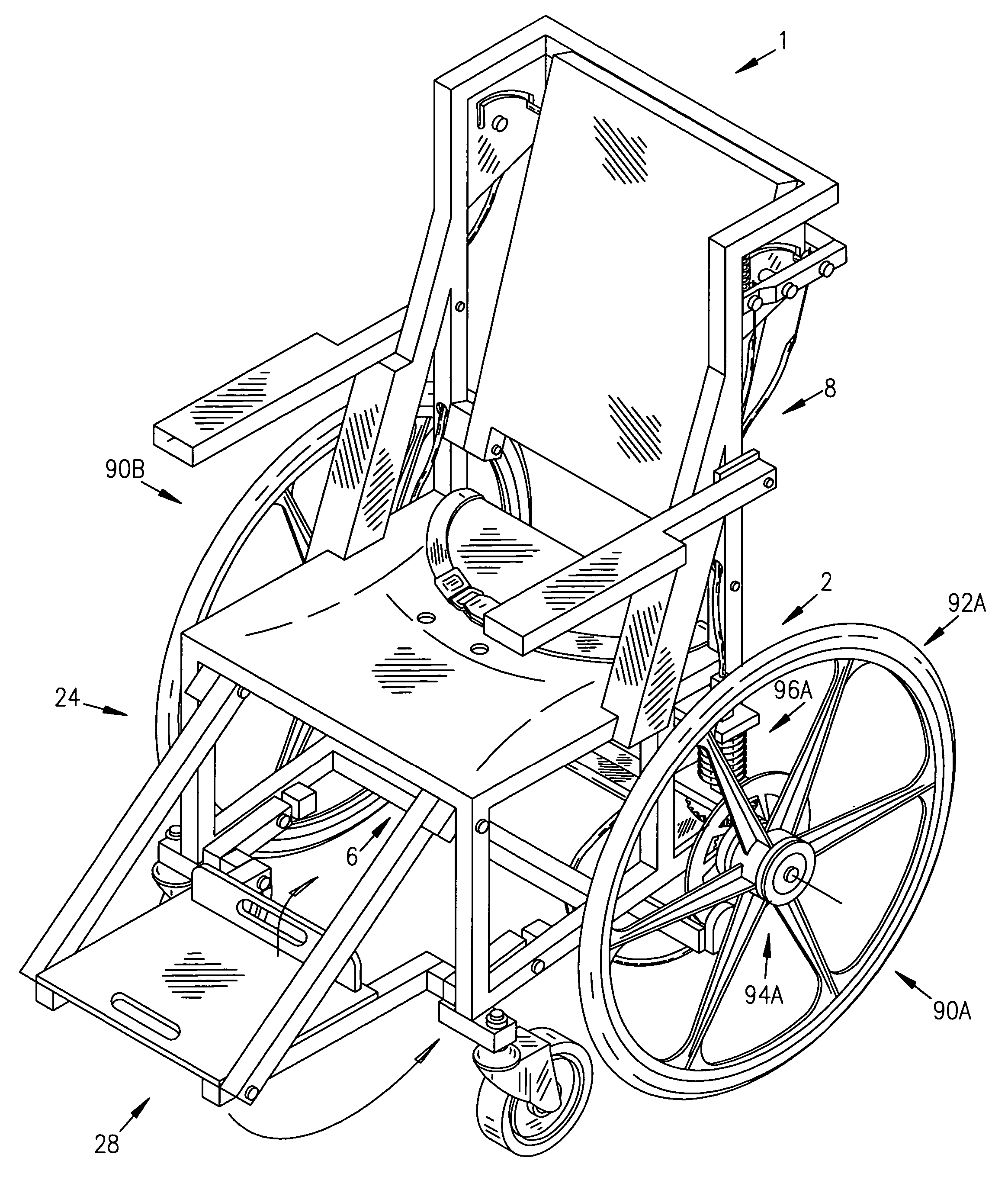
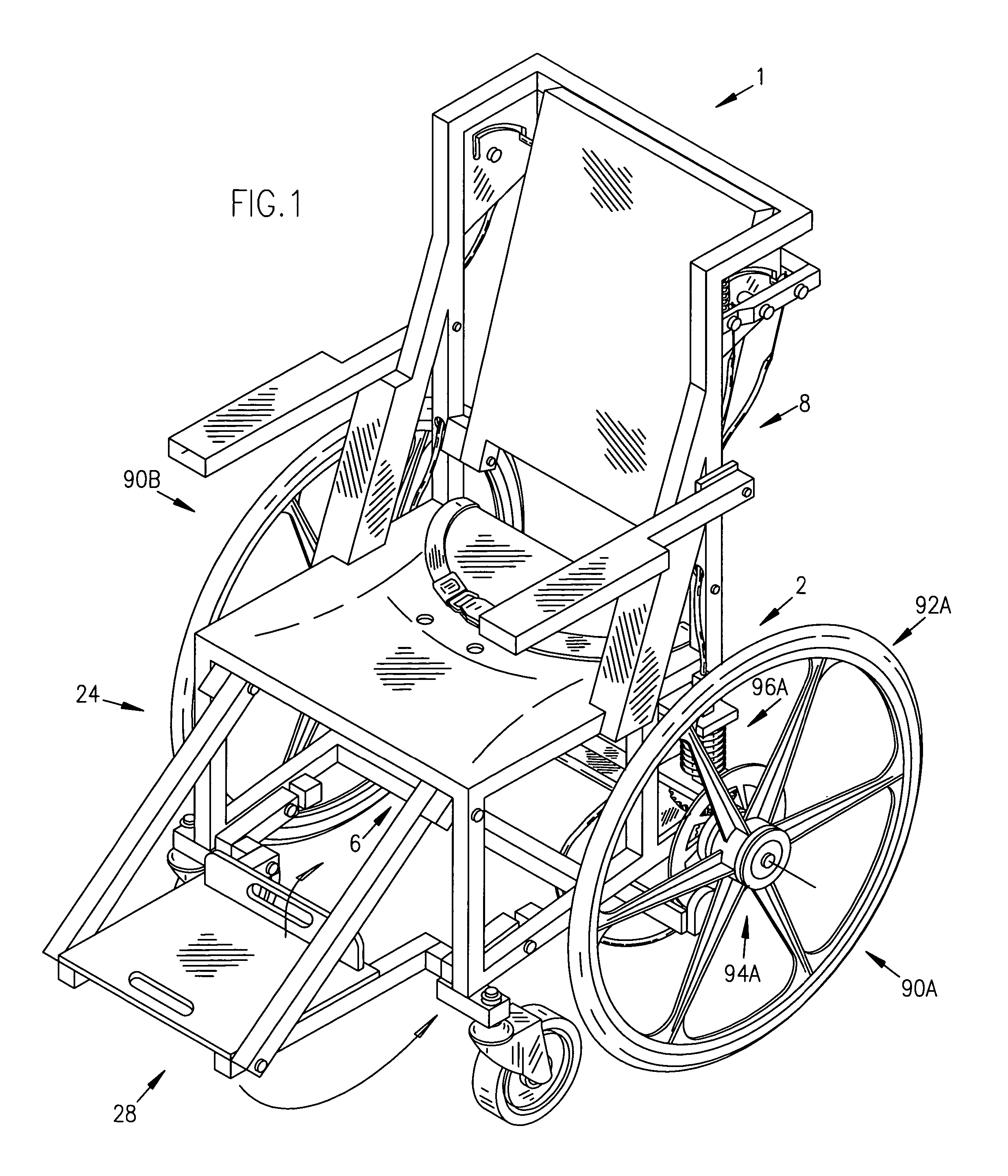
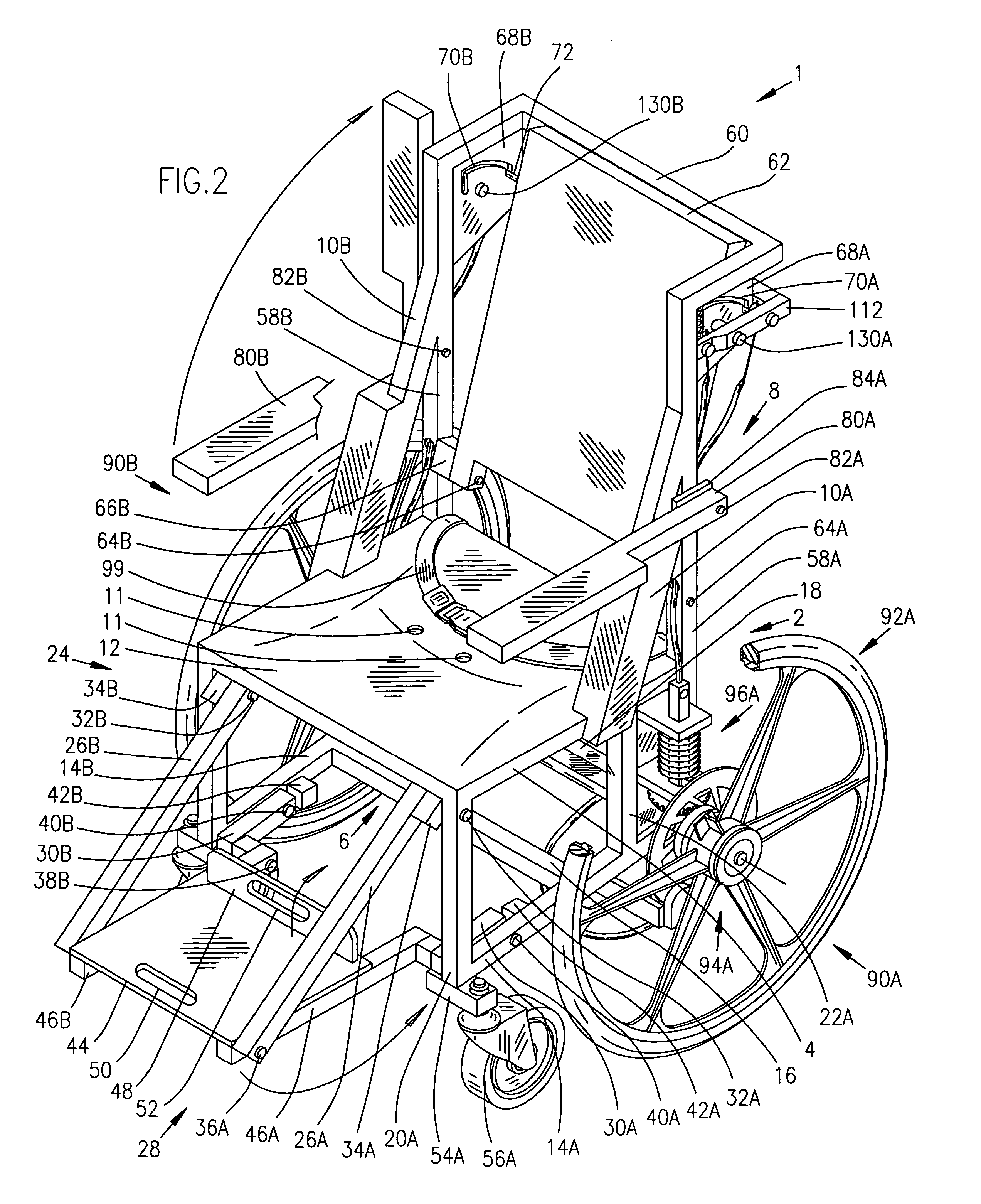
[0042]A typical embodiment of the device of the present invention is illustrated in FIGS. 1-3. A wheelchair 1 has a rigid chair frame 2, which comprises a seat support 4, an opposing pair of forward vertical legs, 20a and 20b, an opposing pair of rear vertical legs 22a and 22b, a back support 8, and armrest supports 10a and 10b. The seat support 4 is a rigid rectangular horizontal bar. A seat 12 is attached to the seat support 4 and contains holes 11 for drainage. The wheelchair can include a seatbelt 99. A chassis 6 supports the chair frame 2. The chassis 6 comprises an opposing pair of parallel horizontal rigid wheel support bars, 14a and 14b, that are interconnected by a perpendicular forward horizontal rigid brace 16 and perpendicular rear horizontal rigid brace 18.

[0043]Referring to FIGS. 2-4, the back support 8 comprises opposing vertical back support bars 58a and 58b, a horizontal U-shaped push-bar handle 60, a seat back 62, and seat back guide plates 68a and 68b. The back su...


PUM


Abstract

An assistive mobility device is provided that includes an automatic positive locking system, which permits an operator to move the assistive mobility device when an actuator is engaged and automatically lock the assistive mobility device when the actuator is disengaged. The assistive mobility device includes a braking system, stowable footrest and armrests, and an adjustable back, which all require the single-handed operation of the operator to function. The collapsible footrest is stowed under the seat permitting an occupant optimal entry into or exit from the assistive mobility device. The assistive mobility device can be formed from non-corrosive materials, including stainless steel, composite fibers, nylon, and plastics, for use in aquatic environments.

Description

CROSS-REFERENCES TO RELATED APPLICATIONS[0001]This application claims the benefit of Provisional Patent Application No. 60 / 542,801, filed Feb. 5, 2004.BACKGROUND[0002]1. Field of Invention[0003]The present invention relates generally to wheelchairs and, more specifically, to assistant-driven wheelchairs. The present invention is related to braking and locking mechanisms for wheelchairs. The present invention is also related to a collapsible footrest.[0004]2. Discussion of Prior Art[0005]A unique set of issues must be addressed for assistive mobility devices, such as an assistant moving a physically disabled person in a wheelchair. An assistant must move the wheelchair user up and down ramps safely, often under adverse environmental conditions. For example, the wheelchair or ramp may be wet from use in rain, a shower, or from pool therapy. The wheelchair must remain immobile while an assistant helps a person into and out of the wheelchair and remain immobile until the assistant is re...

Claims


Application Information

Patent Timeline
Patent Type & Authority Patents(United States)
IPC IPC(8): A61G5/10A61G5/12B62B5/04B62M1/14
CPCA61G5/10A61G5/1067A61G5/12A61G5/1021A61G5/1008A61G5/101A61G5/1024A61G5/1037A61G2005/1054A61G2005/125A61G2005/128B62B5/0404B62B5/0461B62B5/0438A61G5/1054A61G5/125A61G5/128
Inventor STAMPS, DOUGLAS WAYNESTAMPS, JANICE LYNNGIESTING, SAMUEL CHARLESCOOPER, III, EDWARD THOMASSCHENK, DANIEL EDWARDSTOLL, JAROD DANIELNISLEY, ADAM JAY
Owner STAMPS DOUGLAS WAYNE
Why Eureka
Try Eureka