Variable valve timing control apparatus of internal combustion engine

a technology of timing control apparatus and internal combustion engine, which is applied in the direction of valve details, valve arrangements, valve drives, etc., can solve the problems of affecting the control accuracy of the vtc device, the difficulty of accurately maintaining the rotational balance of the vane member, and the difficulty of the operation of the five-blade vane member equipped with the timing variator, so as to reduce the unbalance of rotation and increase the phase

Inactive Publication Date: 2007-07-24
HITACHI LTD
View PDF2 Cites 14 Cited by
  • Summary
  • Abstract
  • Description
  • Claims
  • Application Information

AI Technical Summary

Benefits of technology

[0004]Accordingly, it is an object of the invention to provide a hydraulically-operated five-blade vane member equipped variable valve timing control apparatus of an internal combustion engine, capable of reducing rotational unbalance of the five-blade vane member and ensuring an increased phase change of the vane member relative to a cylindrical housing fixedly connected to either one of an engine crankshaft and a camshaft.

Problems solved by technology

However, in case of a hydraulically-operated vane-type timing variator employing a five-blade vane member having circumferentially equidistant-spaced, five vane blades, there is no blade existing in a position diametrically opposing the first vane blade having a lock-pin bore slidably accommodating therein a lock pin.
Thus, the hydraulically-operated five-blade vane member equipped timing variator has difficulty in accurately maintaining rotational balance of the vane member.
As a result of this, the control accuracy of the VTC device also tends to be deteriorated.

Method used


Image

  • Variable valve timing control apparatus of internal combustion engine
  • Variable valve timing control apparatus of internal combustion engine
  • Variable valve timing control apparatus of internal combustion engine

Examples


Embodiment Construction

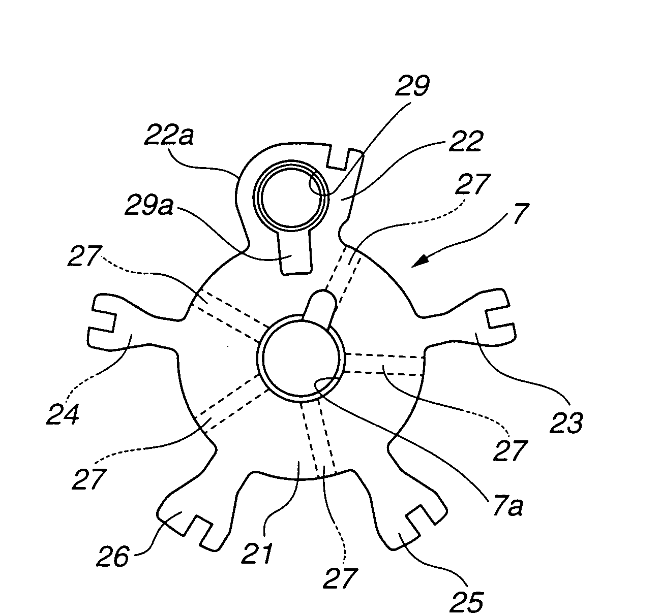
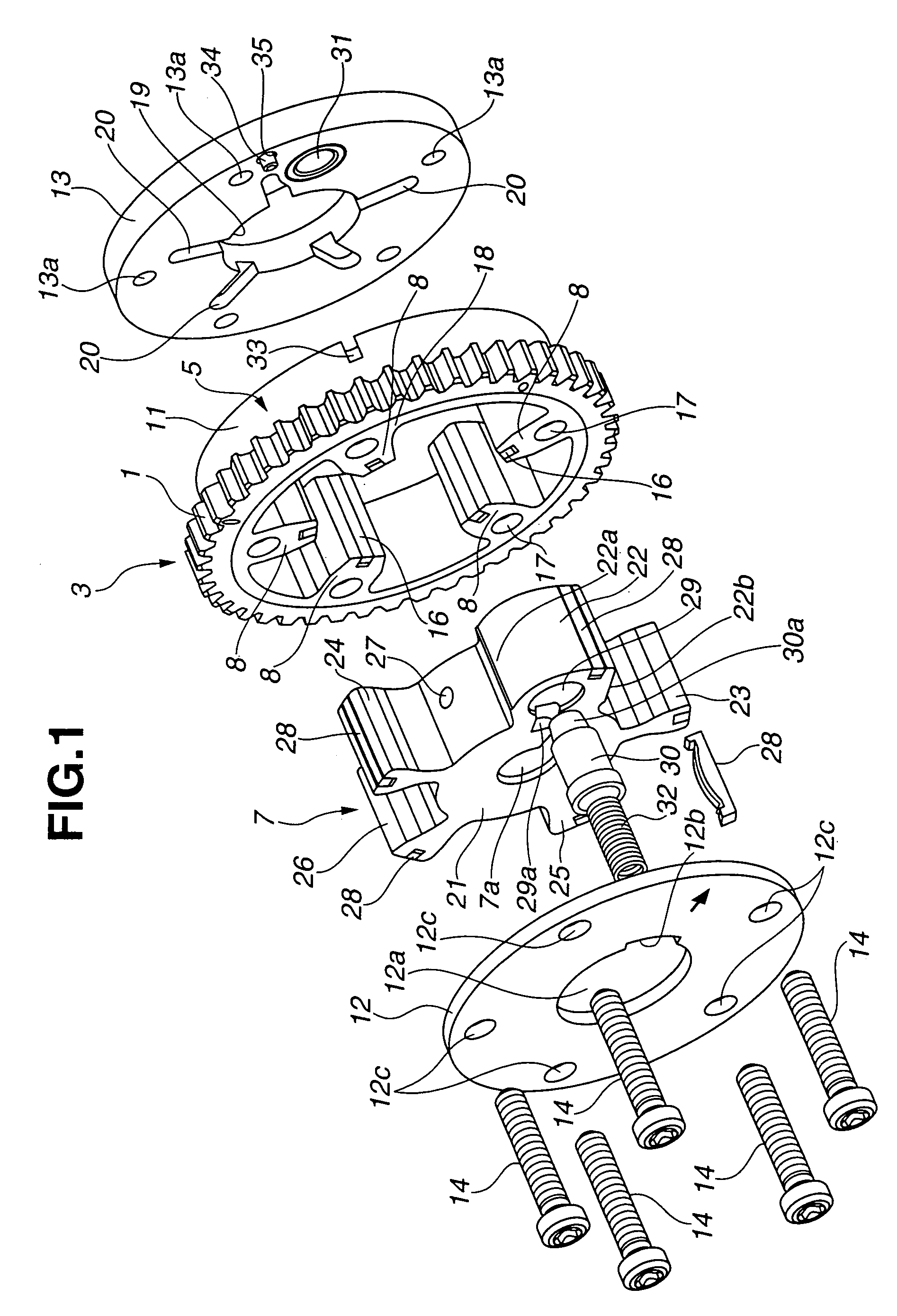
[0016]Referring now to the drawings, particularly to FIGS. 1–5, the variable valve timing control (VTC) apparatus of the embodiment is exemplified in an internal combustion engine with a hydraulically-operated vane-type timing variator.

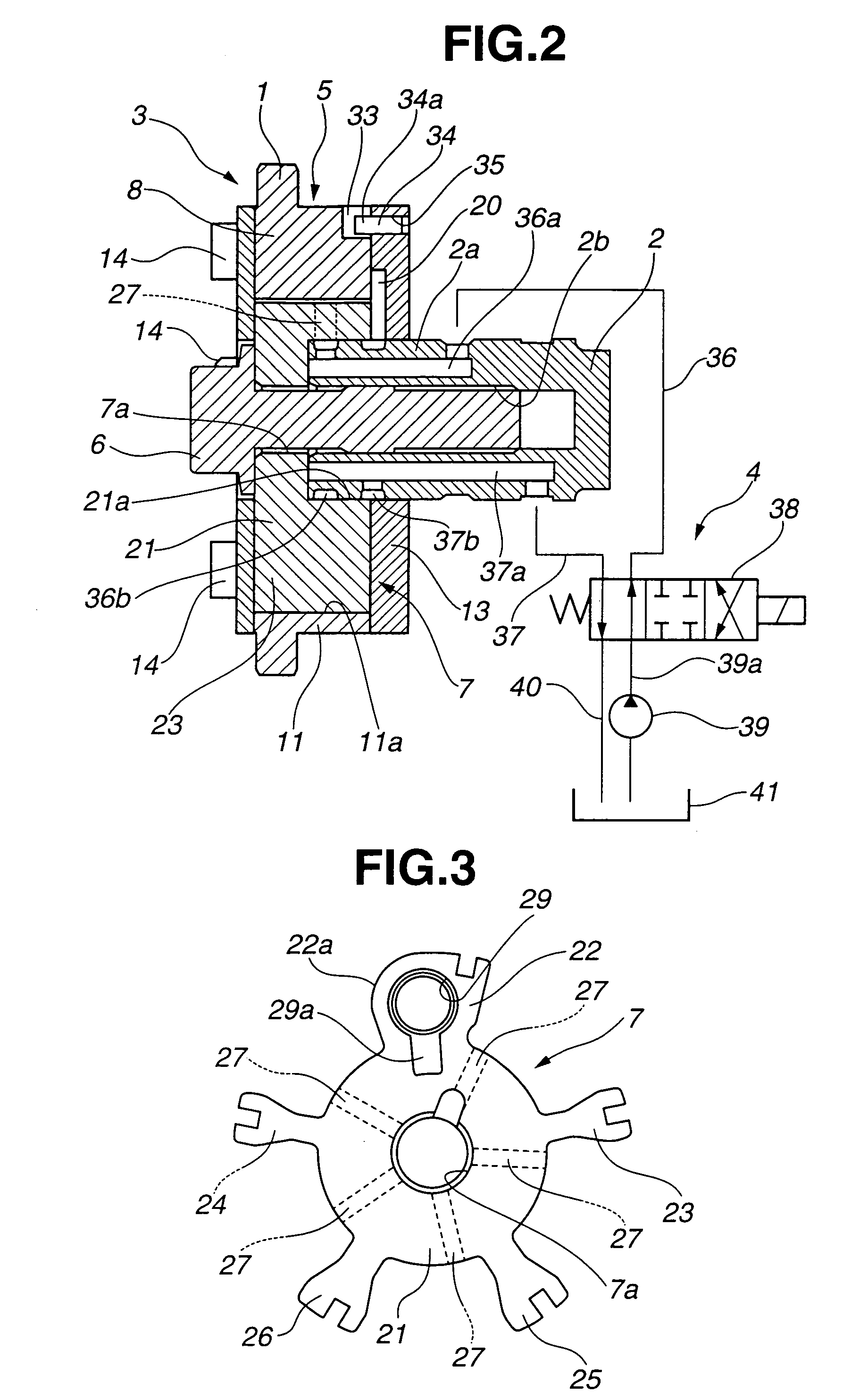
[0017]As best seen in FIG. 2, the VTC apparatus of the embodiment is comprised of a disc-shaped sprocket 1, a camshaft 2, a phase converter 3, and a hydraulic circuit 4. Sprocket 1 serves as a rotary member, which is driven by an engine crankshaft (not shown) via a timing chain. Camshaft 2 is provided to be rotatable relative to sprocket 1. Rotary motion of camshaft 2 relative to sprocket 1 is permitted via phase converter 3. Phase converter 3 is disposed between sprocket 1 and camshaft 2 for converting or changing an angular phase of camshaft 2 relative to sprocket 1. Hydraulic circuit 4 is connected to phase converter 3 to hydraulically operate phase converter 3.

[0018]Camshaft 2 is rotatably supported on a cylinder head (not shown) by means of cam b...


PUM


Abstract

A variable valve timing control apparatus employs a five-blade vane member fixedly connected to a camshaft end and rotatably disposed in a phase-converter housing formed integral with a sprocket driven by an engine crankshaft. Five phase-retard chambers and five phase-advance chambers are defined by five blades of the vane member and the housing, for creating a phase change of the vane member relative to the housing. A circumferential width of each of a first pair of blades, located on both sides of a first blade having a maximum circumferential width, is dimensioned to be less than a circumferential width of each of a second pair of blades, circumferentially spaced apart from the first blade rather than the first pair. The circumferential width of each of the second pair of blades is dimensioned to be less than the maximum circumferential width of the first blade.

Description

TECHNICAL FIELD[0001]The present invention relates to a variable valve timing control apparatus of an internal combustion engine capable of variably adjusting an open-and-closure timing of an engine valve depending on an engine operating condition, and specifically to an automotive variable valve timing control apparatus employing a hydraulically-operated vane-type timing variator capable of varying a relative phase of a camshaft to an engine crankshaft by supplying working fluid (hydraulic pressure) selectively to either one of a phase-advance hydraulic chamber and a phase-retard hydraulic chamber.BACKGROUND ART[0002]In recent years, there have been proposed and developed various variable valve timing control systems each employing a phase converter, such as a hydraulically-operated vane-type timing variator. A hydraulically-operated vane-type timing variator has been disclosed in Japanese Patent Provisional Publication No. 2002-30908 (hereinafter is referred to as “JP2002-30908”)....

Claims


Application Information

Patent Timeline
Patent Type & Authority Patents(United States)
IPC IPC(8): F01L1/34
CPCF01L1/022F01L1/3442F01L1/024F01L2001/34426F01L2001/34469F01L2103/00F01L2303/00
Inventor SUGA, SEIJITSUKADA, TOMOYA
Owner HITACHI LTD
Why Eureka
Try Eureka