
Transformer having a stacked core with a cruciform leg and a method of making the same

a technology of transformers and cruciforms, which is applied in the field of transformers, can solve the problems of more wasted steel and difficult manufacturing

Inactive Publication Date: 2007-08-14
ABB (SCHWEIZ) AG
View PDF16 Cites 9 Cited by
  • Summary
  • Abstract
  • Description
  • Claims
  • Application Information

AI Technical Summary

Benefits of technology

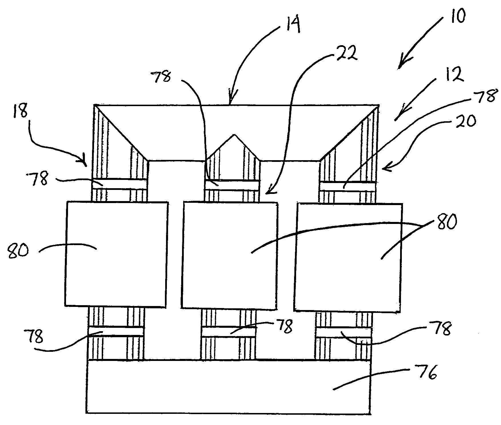
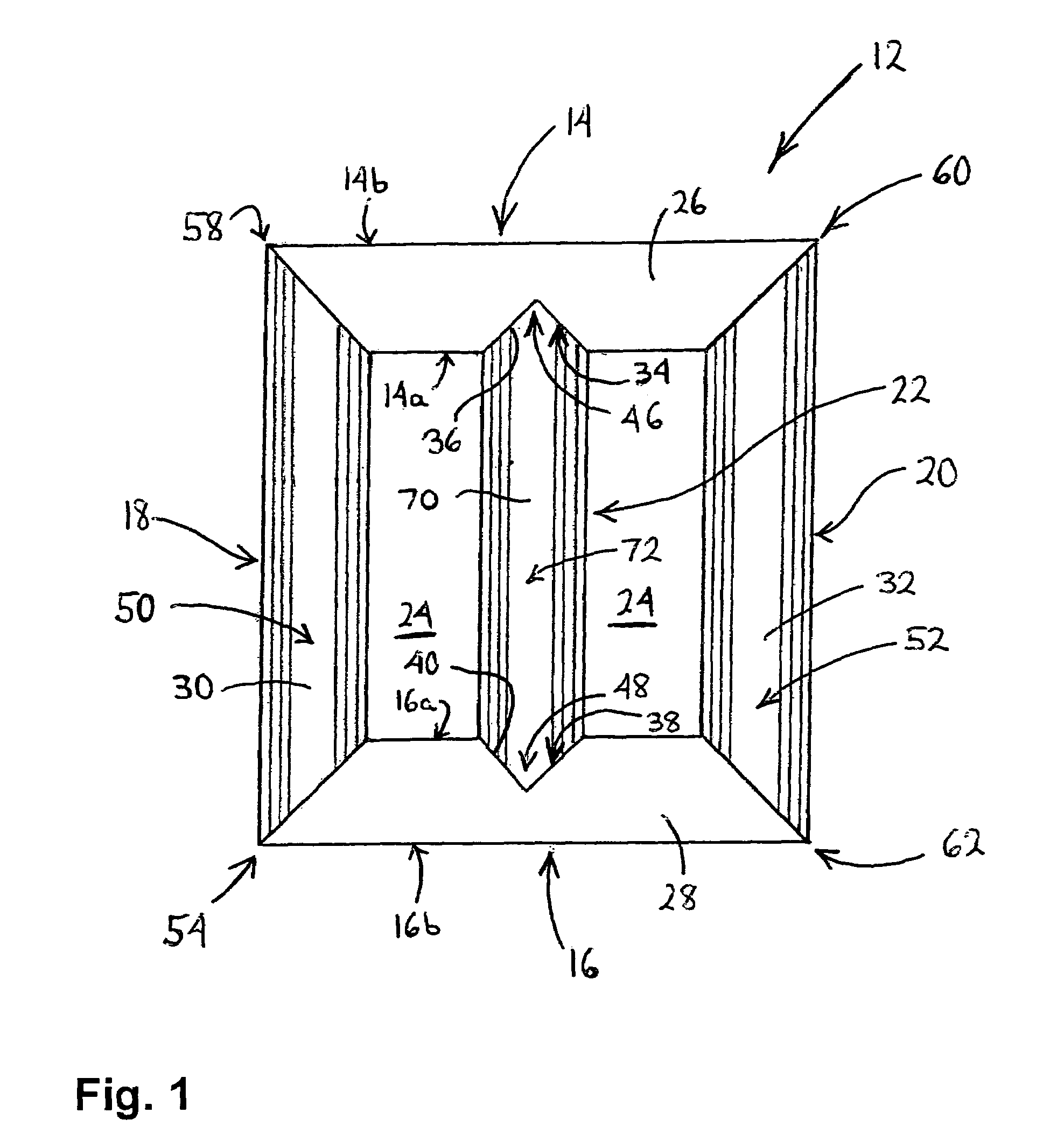
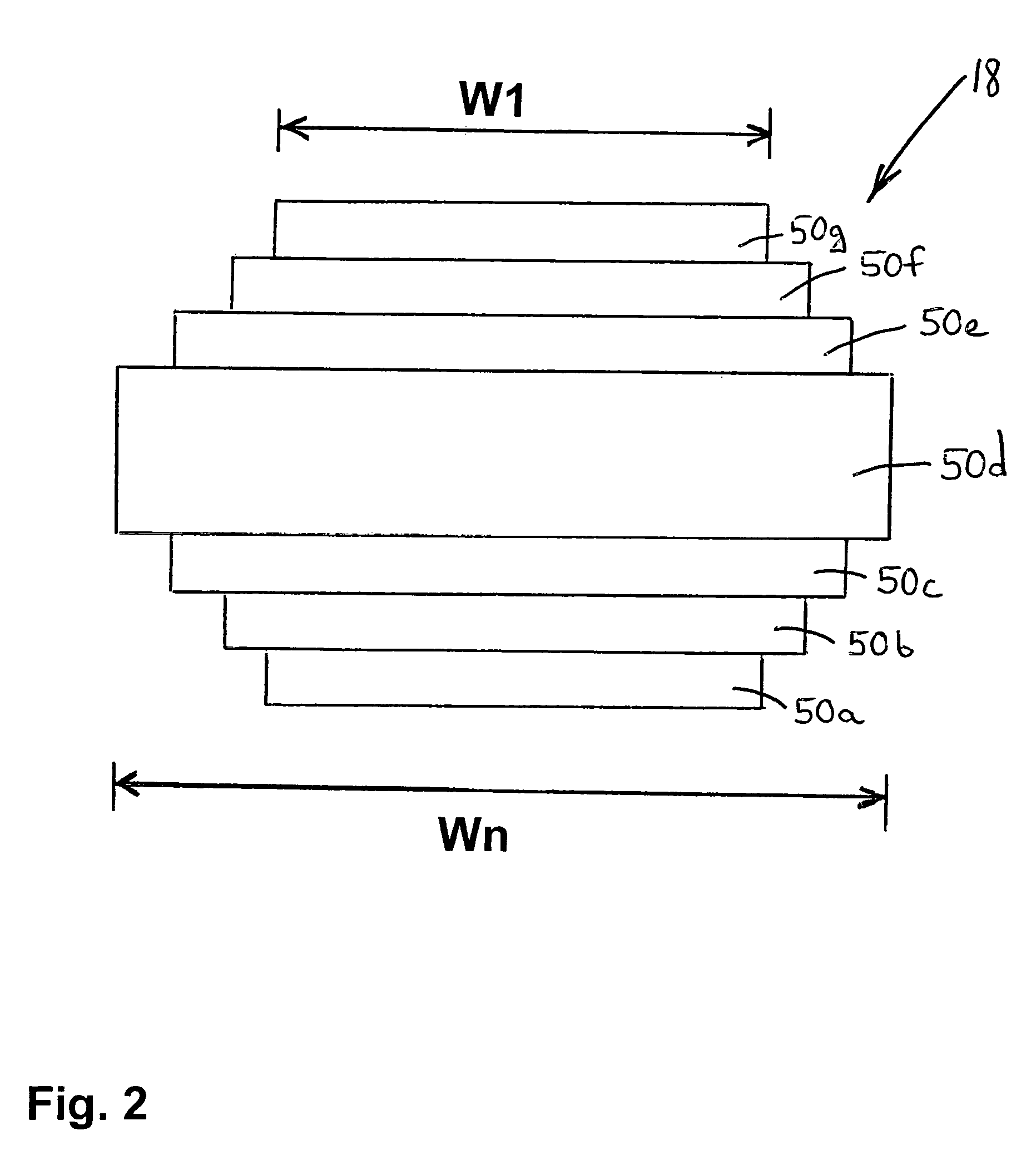
The present invention provides a transformer with a stacked core that has a first yoke and a second yoke with a groove between them. The first yoke is made up of plates with a notch on their inner side, while the second yoke is made up of plates with different widths. The inner leg is made up of plates with different widths and a cruciform cross-section. The transformer has a rectangular cross-section and is mounted with a coil winding. The technical effect of this invention is to provide a more efficient and compact transformer with improved performance.

Problems solved by technology

Although a stacked core having a cruciform cross-section, such as the core of the DeLaurentis et al. patent, provides additional support and strength, such a core is typically more difficult to manufacture and results in more wasted steel.

Method used


Image

  • Transformer having a stacked core with a cruciform leg and a method of making the same
  • Transformer having a stacked core with a cruciform leg and a method of making the same
  • Transformer having a stacked core with a cruciform leg and a method of making the same

Examples


second embodiment

[0033]Referring now to FIG. 7, there is shown a core 84 embodied in accordance with the present invention. The core 84 has substantially the same construction, is constructed in substantially the same manner and may be used in a transformer in substantially the same manner as the core 12, except for the differences set forth below. Instead of having the inner leg 22, the core 84 has an inner leg 86, which comprises a first stack 88 of inner leg plates 90 and a second stack 92 of inner leg plates 90. The first and second stacks 88, 92 abut each other along a seam 94 that extends in the longitudinal direction of the inner leg 86. Upper ends of the first and second stacks 88, 92 are disposed in the upper groove 46 of the upper yoke 14 and lower ends of the first and second stacks 88, 92 are disposed in the lower groove 48 of the lower yoke 16. Each of the inner leg plates 90 has a unitary construction and is trapezoidal in shape. In each of the inner leg plates 90, opposing ends of the...

third embodiment

[0036]Referring now to FIG. 8, there is shown a core 100 embodied in accordance with the present invention. The core 100 has substantially the same construction, is constructed in substantially the same manner and may be used in a transformer in substantially the same manner as the core 12, except for the differences set forth below. Instead of having only one inner leg 22, like the core 12, the core 100 has three inner legs 22. In addition, the core 100 has first and second outer legs 102, 104 with rectangular cross-sections, instead of cruciform cross-sections, as in the core 12. Also, the core 100 has upper and lower yokes 106, 108, each of which is comprised of a plurality of stacks of plates, instead of only a single stack, as in the core 12. Further, the upper yoke 106 of the core 100 has three upper grooves 46a, b, c and the lower yoke 108 of the core 100 has three lower grooves 48a, b, c, instead of a single upper groove 46 and a single lower groove 48, as in the core 12. Wi...


PUM

PropertyMeasurementUnit
thicknessaaaaaaaaaa
anglesaaaaaaaaaa
widthaaaaaaaaaa

Abstract

The present invention is directed to a transformer having a stacked core, which includes upper and lower yokes and first and second outer legs. The core also includes one or more inner legs. Each of the upper and lower yokes is formed from a stack of plates and has a rectangular cross-section. Each inner leg is formed from a stack of plates and has a cruciform cross-section. Each of the first and second outer legs is formed from a stack of plates and may have a cruciform cross-section.

Description

FIELD OF THE INVENTION[0001]The invention relates to transformers and more particularly, to transformers having a stacked core with a cruciform leg and methods of making the same with reduced waste.BACKGROUND OF THE INVENTION[0002]A stacked transformer core is comprised of thin metallic laminate plates, such as grain oriented silicon steel. This type of material is used because the grain of the steel may be groomed in certain directions to reduce the magnetic field loss. The plates are stacked on top of each other to form a plurality of layers. A stacked core is typically rectangular in shape and can have a rectangular or cruciform cross-section. A cruciform cross-section increases the strength of a stacked core. In addition, a core leg having a cruciform cross-section provides more surface area for supporting a coil. An example of a conventional stacked transformer core having a cruciform cross-section is shown in U.S. Pat. No. 4,283,842 to DeLaurentis et al. The core of the DeLaur...

Claims


Application Information

Patent Timeline
Patent Type & Authority Patents(United States)
IPC IPC(8): H01F27/24
CPCH01F27/245H01F41/0233H01F27/263Y10T29/4902Y10T29/49073Y10T29/49078
Inventor PAULEY, JR., WILLIAM E.SARVER, CHARLIE H.HORTON, JR., RUSH B.
Owner ABB (SCHWEIZ) AG
Learn More