
O-ring for incrementally adjustable incision liner and retractor

a retractor and incision liner technology, applied in the field of surgical wound protectors, can solve the problem that the side of the wound during surgery is inherently susceptible to bacteria infection, and achieve the effect of shortening the sleev

Inactive Publication Date: 2005-10-13
MCT II LLC
View PDF32 Cites 22 Cited by
  • Summary
  • Abstract
  • Description
  • Claims
  • Application Information

AI Technical Summary

Benefits of technology

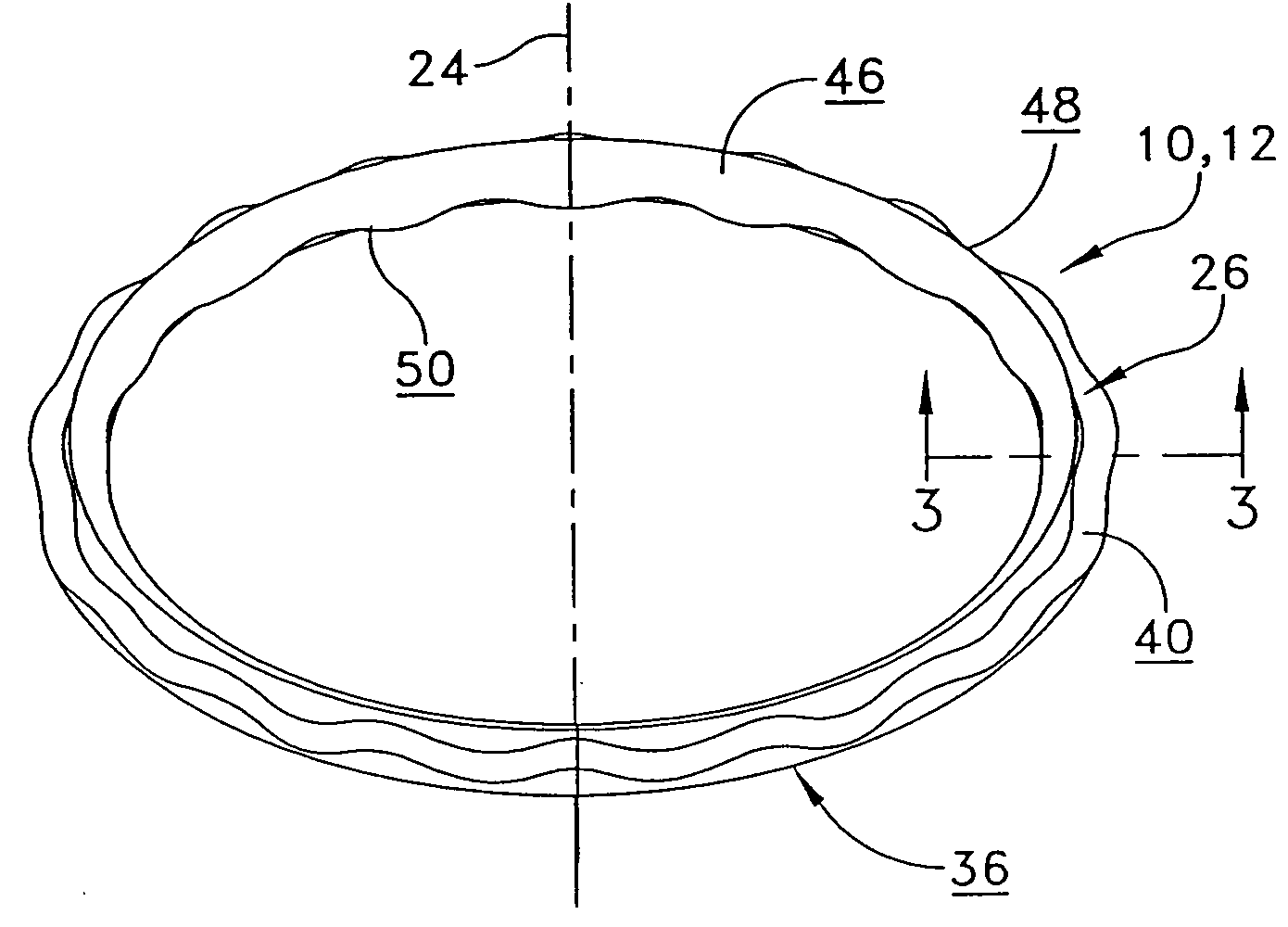
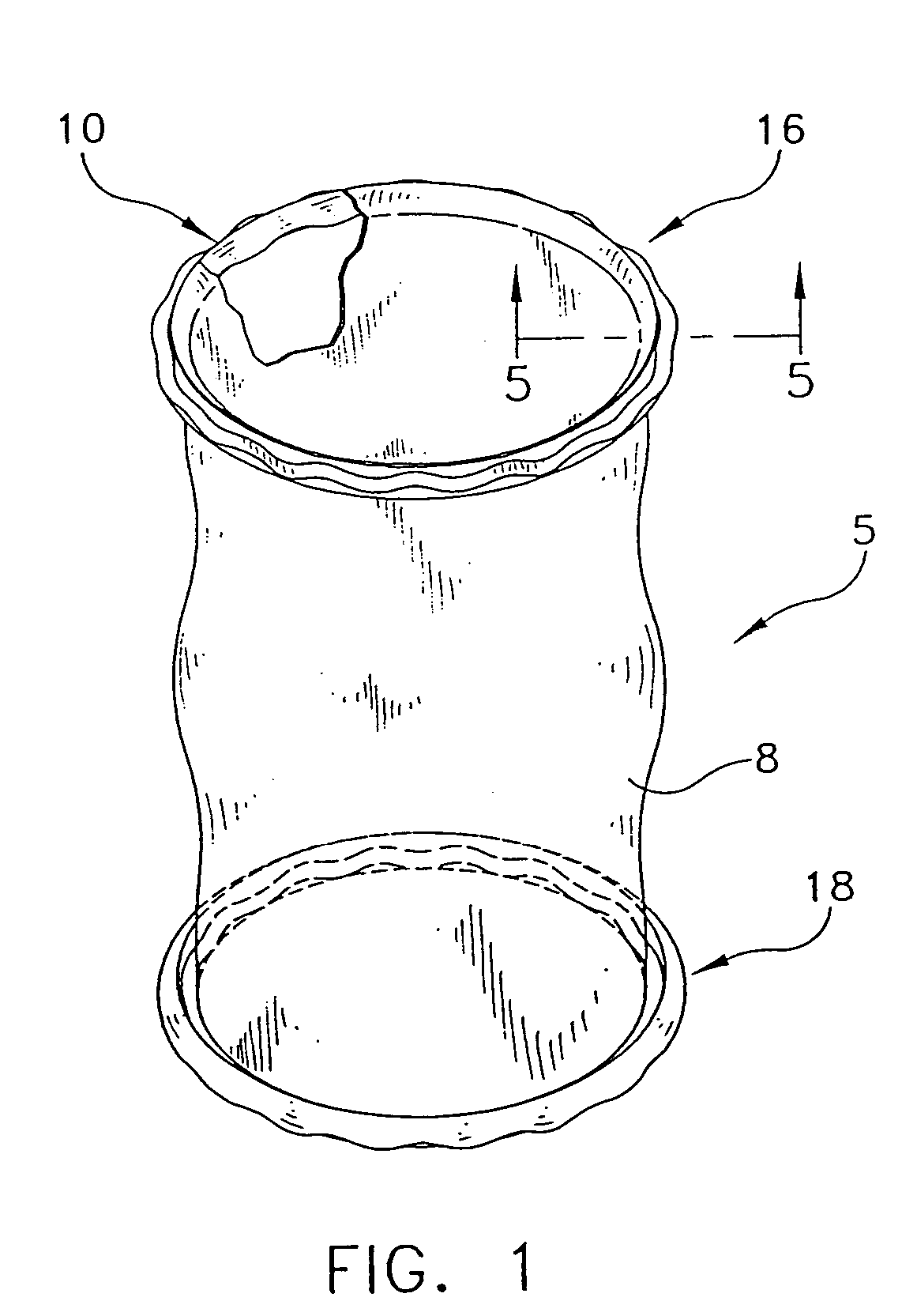
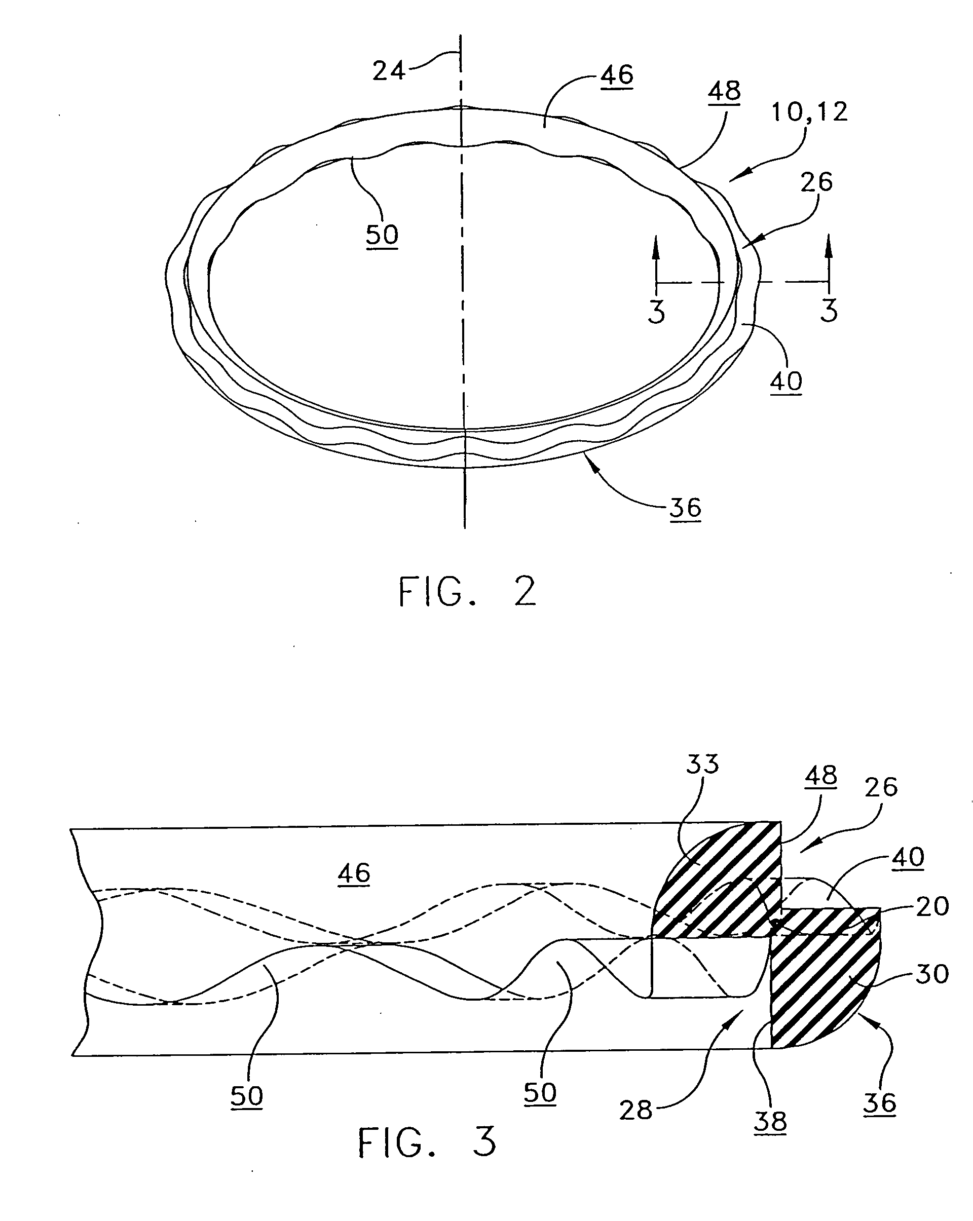
[0008] An improved adjustable surgical wound protector is also provided that comprises an elongate open-ended tube formed of a pliable material that is impervious to solid and fluid contaminants for inserting lengthwise into a surgical incision. Two O-rings are one each secured around the open ends of the tube. The O-rings have a resilient configuration for overlapping the inner edge of the wound and for squeezing into an oblong shape that is insertable with a lengthwise portion of the sleeve adjacent to one of the O-rings in the surgical incision. Advantageously, at least one of the O-rings comprises at least one recess for enabling selected snap-action rolling of the at least one O-ring for rolling the remaining lengthwise portion of the sleeve on itself about the O-ring to shorten the sleeve in predetermined increments and to resist subsequent lengthening, whereby the sleeve length can be adjusted before or after placement in the wound.

Problems solved by technology

The sides of a wound during surgery are inherently susceptible to bacterial infection if touched by contaminated substances such as diseased body parts and fluids as they pass through the wound.

Method used


Image

  • O-ring for incrementally adjustable incision liner and retractor
  • O-ring for incrementally adjustable incision liner and retractor
  • O-ring for incrementally adjustable incision liner and retractor

Examples


Embodiment Construction

[0078] This description of preferred embodiments is intended to be read in connection with the accompanying drawings, which are to be considered part of the entire written description of this invention. In the description, relative terms such as “horizontal,”“vertical,”“up,”“down,”“top” and “bottom” as well as derivatives thereof (e.g., “horizontally,”“downwardly,”“upwardly,” etc.) should be construed to refer to the orientation as then described or as shown in the drawing figure under discussion. These relative terms are for convenience of description and normally are not intended to require a particular orientation. Terms including “inwardly” versus “outwardly,”“longitudinal” versus “lateral” and the like are to be interpreted relative to one another or relative to an axis of elongation, or an axis or center of rotation, as appropriate. Terms concerning attachments, coupling and the like, such as “connected” and “interconnected,” refer to a relationship wherein structures are secu...


PUM


Abstract

An O-ring is provided for use in an adjustable surgical wound protector having a solid cross-section including a cross-sectional center that is spaced from a central longitudinal axis and a resilient configuration for squeezing into an oblong shape that is insertable into a surgical incision. At least one recess is defined in the O-ring that is selectively sized and shaped to enable a snap-action rolling of the O-ring about the cross-sectional center in predetermined increments. The recess may comprise various cross-sectional shapes, such as, at least one circumferential groove, a plurality of circumferentially positioned recesses, or be shaped such that the O-ring comprises a cruciform cross-section. An improved incrementally adjustable apparatus for protecting an incised wound from exposure to bacterial and other harmful contaminants is also provided including a pair of resilient O-rings connected to opposite ends of an impermeable pliable sleeve. One of the O-rings is formed to engage the inner edge of the wound with a portion of the sleeve above the wound capable of being rolled onto the other ring to draw the remaining sleeve portion contiguous with the sides of the wound.

Description

FIELD OF THE INVENTION [0001] The present invention relates generally to surgical wound protectors, and more particularly to an adjustable surgical wound protector for use in protecting incised cavity walls of various thicknesses from harmful contaminants during surgery. BACKGROUND OF THE INVENTION [0002] The sides of a wound during surgery are inherently susceptible to bacterial infection if touched by contaminated substances such as diseased body parts and fluids as they pass through the wound. Therefore extreme care must be exercised to insure that the exposed sides of an incision are completely covered by a material impervious to solids and fluids containing bacteria and other contaminants before surgery proceeds. [0003] Various techniques have been used to insulate any incised tissue from exposure. One form of protection for relatively large incisions typically employs soft cotton sponges held against the sides of the wound by metal retractors to minimize contamination as well ...

Claims


Application Information

Patent Timeline
IPC IPC(8): A61B17/02A61B17/08A61B17/34A61B19/00
CPCA61B17/0293A61B19/38A61B17/3431A61B17/3423A61B90/40
Inventor RAMBO, ROBERT D.
Owner MCT II LLC
Learn More