Arrangement of operating elements on a microscope

a technology of operating elements and microscopes, applied in the field of microscopes, can solve the problems of inconvenient limitation of four buttons and unsatisfactory operation concepts

Active Publication Date: 2007-08-21
CARL ZEISS MICROSCOPY GMBH
View PDF13 Cites 14 Cited by
  • Summary
  • Abstract
  • Description
  • Claims
  • Application Information

AI Technical Summary

Benefits of technology

[0006]Thus, in contrast to the aforementioned known approach, the invention leaves the rotary knob completely free and arranges the buttons staggered along the axis of rotation as well as with operating surfaces arranged parallel to the axis of rotation, such that the operating surfaces substantially join up with the rotary knob along the axis of rotation. Since the fingers need not rest on the buttons all the time, the number of buttons may be considerably much larger than possible in the prior art. Thus, the arrangement according to the invention allows to provide many more buttons than in the prior art.
[0007]Surprisingly, the construction according to the invention additionally allows the rotary knob to be grasped in almost any desired manner. The hand and, in particular, the fingers of the hand need no longer be lifted from the rotary knob in order to allow operation of the buttons. The compulsory position of the hand as given in the prior art is thus eliminated. A user may now grasp the rotary knob as desired. It is possible, in particular, to grasp the rotary knob in a manner allowing several fingers to contact the peripheral surface of the rotary knob substantially parallel to the axis of rotation. Operation of the push buttons may be achieved by simply shifting the fingers toward the microscope, i.e. along the axis of rotation.
[0009]The arrangement of the buttons according to the invention may be realized in a microscope by providing the stand with an attachment having the outline of the rotary knob. In order to be able to provide the construction according to the invention also in existing designs of stands, in particular without changing molds, it is convenient to arrange the buttons in an intermediate ring, which is located between the microscope housing and the rotary knob. On a conventional microscope, said intermediate ring may be inserted between the housing and the rotary knob or the setwheel. This makes operating elements easily accessible for all fingers without having to let go of the rotary knob.
[0012]In the aforementioned realization by means of an intermediate ring, it is possible for the user to adjust the positions of the buttons if the intermediate ring is fixable in different rotational positions about the axis of rotation. This may be achieved, for example, by enabling the rotary knob with the intermediate ring to be released from the microscope and to be placed thereon in different angular positions.
[0013]An intermediate ring that can be infinitely adjusted in different rotational positions and fixed in any desired rotational position is particularly comfortable. In one embodiment, the intermediate ring is rotatably supported on the housing and can be fixed by means of a clamping mechanism, e.g. a setscrew or a clamping wedge (in particular, by means of a clamping slide located in the peripheral surface of the intermediate ring).

Problems solved by technology

However, it has turned out that this operational concept is not always satisfactory.
Moreover, in terms of design, the limitation to four buttons is inconvenient.

Method used


Image

  • Arrangement of operating elements on a microscope
  • Arrangement of operating elements on a microscope
  • Arrangement of operating elements on a microscope

Examples


Embodiment Construction

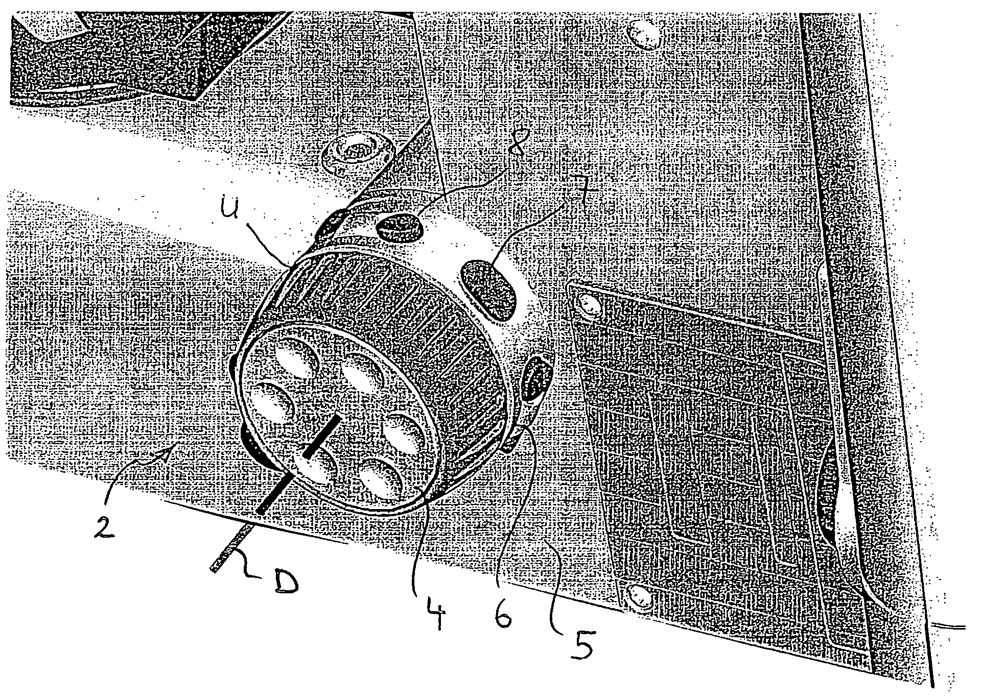
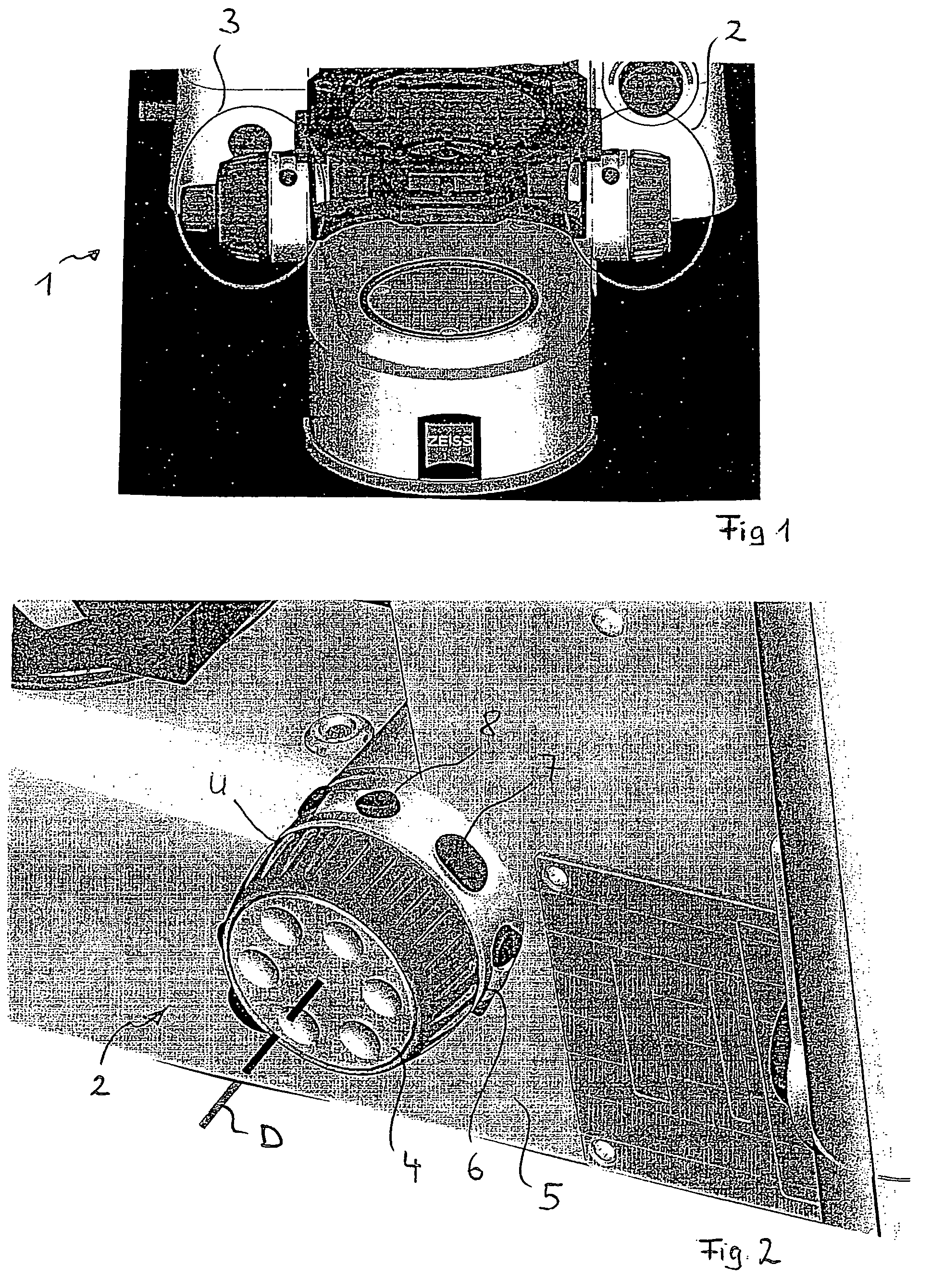
[0018]FIG. 1 shows a perspective view of the lower part of a microscope stand on which a rotary knob 2 or a setwheel unit 3 for focus adjustment is provided in a conventional manner. The setwheel unit 3 comprises a large setwheel for fine adjustment as well as, arranged coaxially thereto, a setwheel for coarse adjustment. In the described embodiment, the rotary knob 2 merely has a single-step design for fine adjustment; for the following description, it is only important that the rotary knob 2 is operated by rotation.

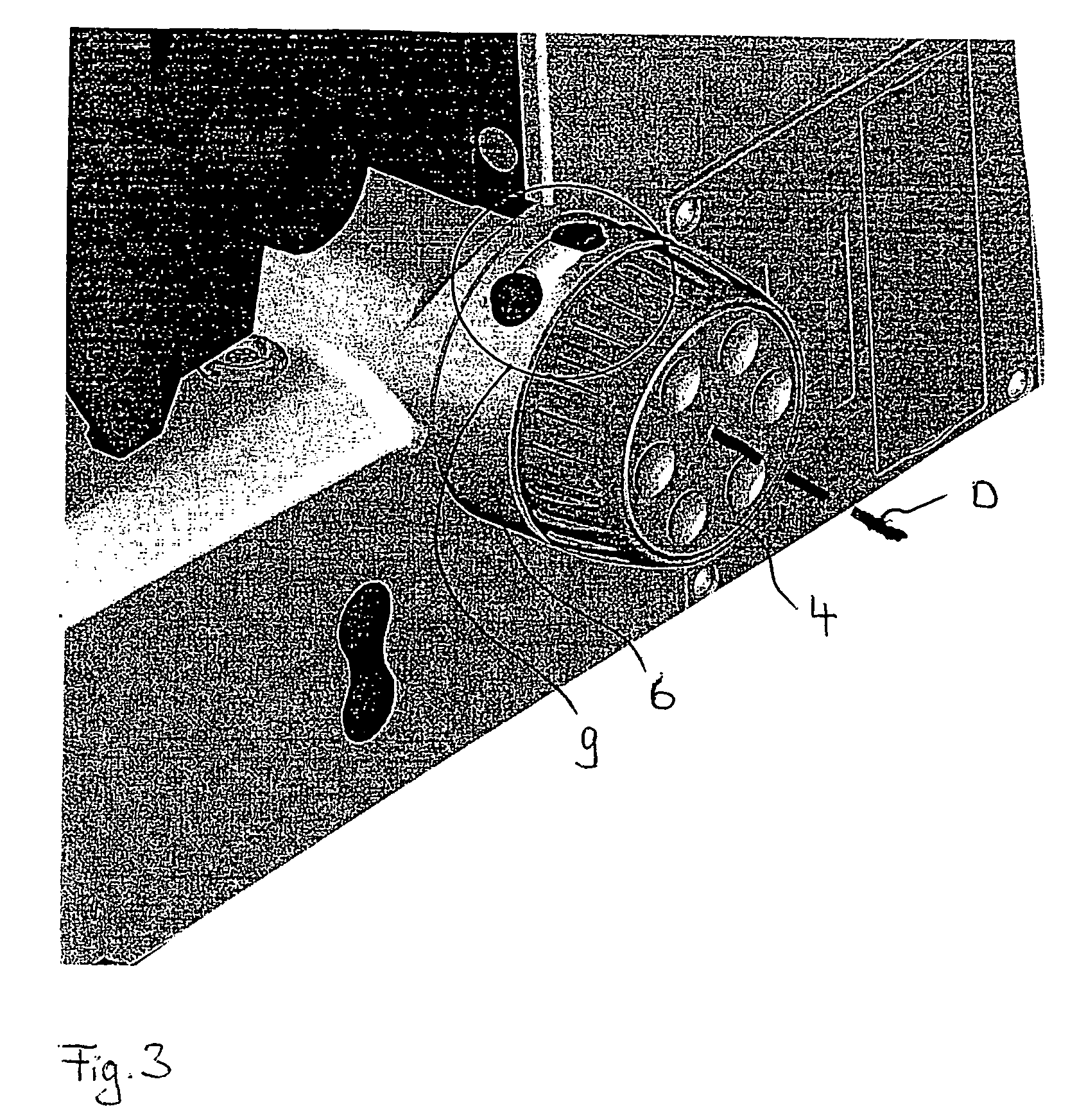
[0019]Both in the setwheel unit 3 and in the rotary knob 2, an intermediate ring 6 is inserted between the setwheel unit or the rotary knob and the housing wall of the microscope stand, said intermediate ring 6 being shown, by way of example, for the rotary knob 2 in FIG. 2. The intermediate ring 6 is arranged between the head 4 of the rotary knob 2 and has an external diameter that corresponds substantially to the external diameter of the head 4. In this manner, the in...


PUM


Abstract

What is described is a microscope comprising at least one rotary knob, which is rotatable about an axis of rotation, for operation of actuating elements and comprising a plurality of buttons for control of electrical components, said buttons being arranged in the region of the rotary knob, wherein the buttons comprise operating surfaces, which are located substantially parallel to the axis of rotation and on the outline of the rotary knob, as viewed along the axis of rotation.

Description

BACKGROUND[0001]The invention relates to a microscope comprising at least one rotary knob, which is rotatable about an axis of rotation, for operating an actuating element and comprising several buttons arranged in the vicinity of the rotary knob, said buttons serving to control electrical components.[0002]Such a microscope is known, for example, from U.S. Pat. No. 5,000,555 wherein a rotary knob for focus operation is provided on the stand of the microscope, said handle being surrounded by a plurality of electric buttons. The buttons are associated with the fingers of the hand of an operator. Thus, for example, one button is provided for the thumb. This button is located on a housing part which surrounds the coarse focusing rotary handle around 120°. Using the ball of the thumb, the operator can operate the rotary handle within the remaining sector, which is about 60° in size, for coarse focusing, while at the same time reaching the corresponding push button located above the rotar...

Claims


Application Information

Patent Timeline
Patent Type & Authority Patents(United States)
IPC IPC(8): G02B21/00
CPCG02B21/24Y10T74/2084
Inventor WAGENER, MICHAELKRAMER, PETER
Owner CARL ZEISS MICROSCOPY GMBH
Why Eureka
Try Eureka