Computer-Implemented Method For Designing A Manufacturable Garment

Active Publication Date: 2017-04-20
NUEVOLUTION AS +1
View PDF0 Cites 11 Cited by
  • Summary
  • Abstract
  • Description
  • Claims
  • Application Information

AI Technical Summary

Benefits of technology

The invention is about a system that allows a designer to create digital models of garments and view them from different angles. This system allows the designer to create shapes and see if they fit without being limited by previous knowledge of garment design. The system eliminates the need for tedious positioning of panels and improves computational efficiency by eliminating the need for a seam closing phase. The "technical effects" of this invention are improved design flexibility and efficiency.

Problems solved by technology

Moreover, manually arranging the patterns around the manikin and defining the seams are tedious and time-consuming operations and they require the execution, by the CAD system, of a “seam closing” phase, before the garment is actually in a position to drape by physical forces (gravity, wind) onto the manikin.
The seam closing phase is problematic and costly because it involves large forces to pull the seams shut.
This is only suitable to the design of tight-fitting garments such as underwear or swimsuits.
Otherwise stated, it cannot be ensured that the virtual garments obtained by applying these methods can be decomposed into developable panels.
Therefore they are of little use in designing garments to be manufactured in the real world and, in virtual-reality applications, they may lead to the design of unrealistic virtual garments.

Method used


Image

  • Computer-Implemented Method For Designing A Manufacturable Garment
  • Computer-Implemented Method For Designing A Manufacturable Garment
  • Computer-Implemented Method For Designing A Manufacturable Garment

Examples


Embodiment Construction

[0048]A description of example embodiments of the invention follows.

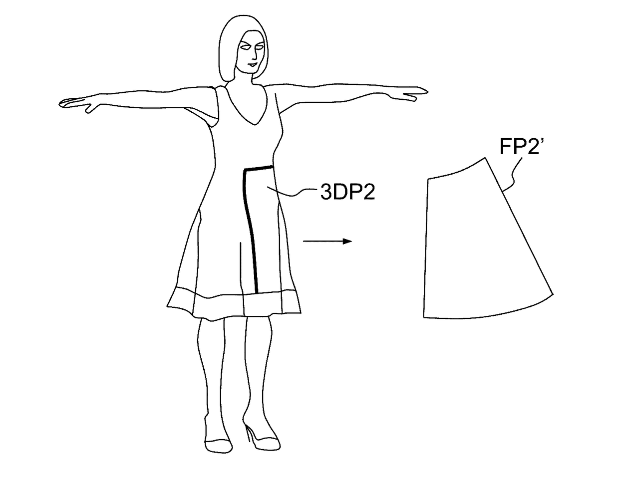
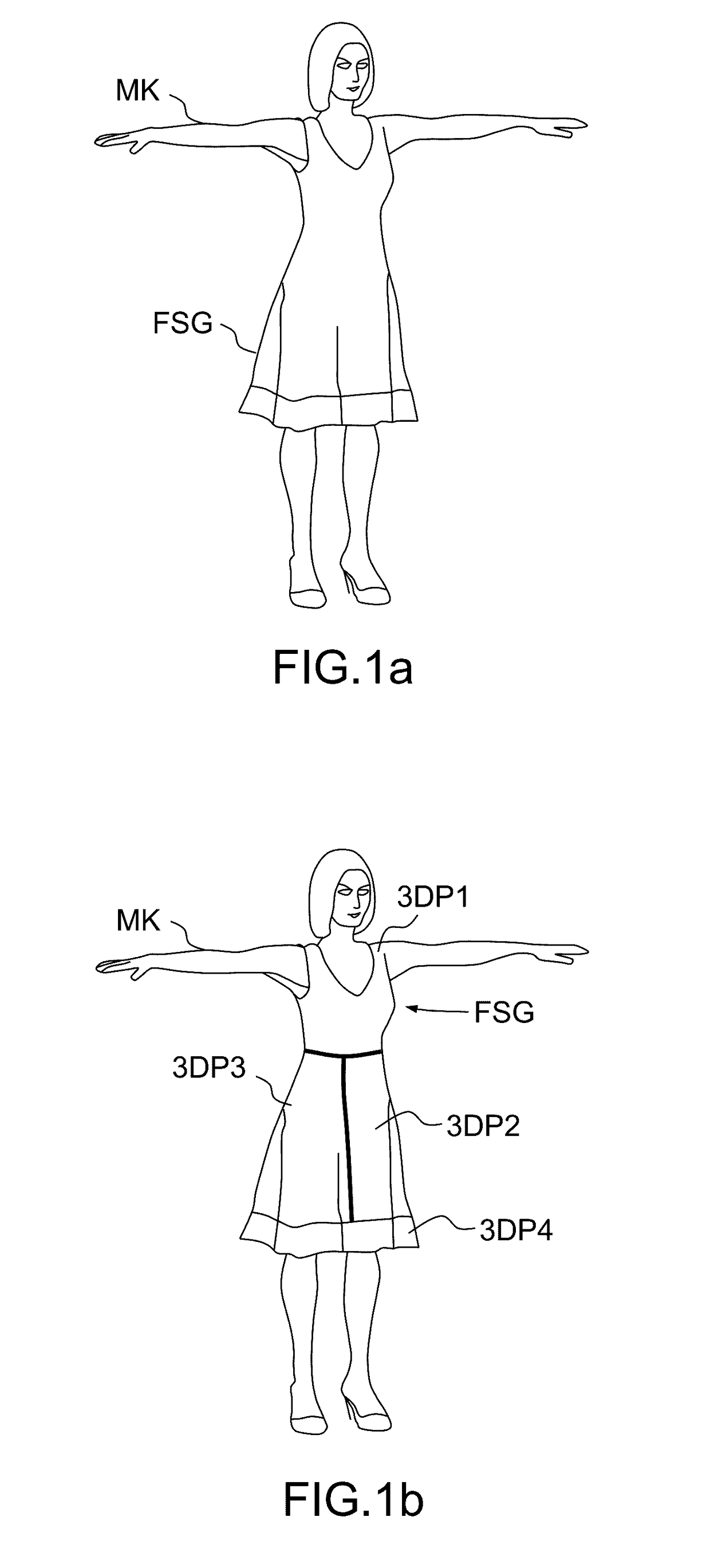
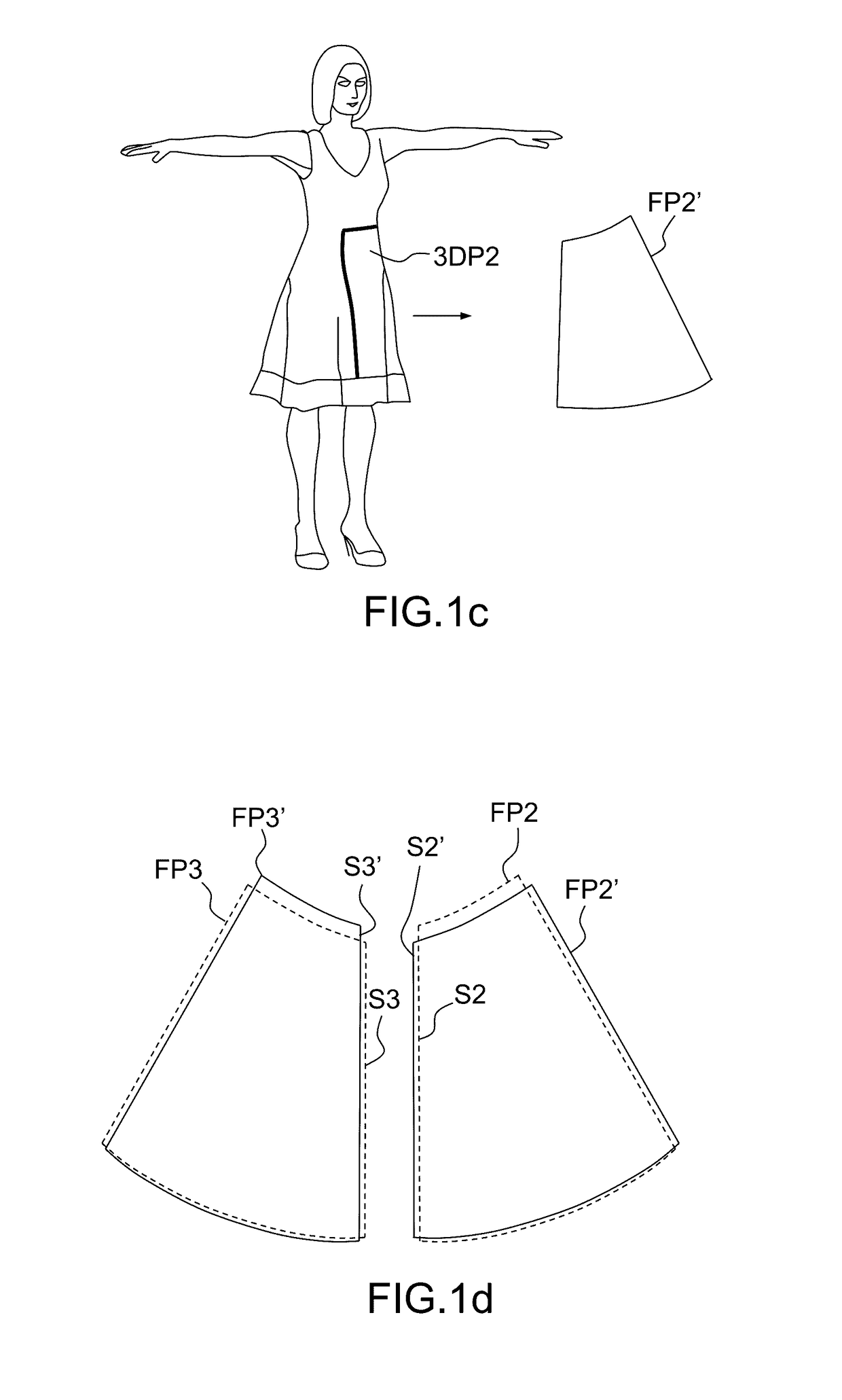
[0049]As illustrated on FIGS. 1a, 1b and 2, the inventive method begins (step a, sub-step al on the flow-chart of FIG. 2) by providing to a CAD system a digitally modeled 3D shape FSG representing a garment. The shape is “free”, i.e. it needs not being constrained by any specific manufacturability requirement. The shape can be sketched by the user on a suitable avatar, or digitally-modeled 3D manikin MK, using e.g. one of the techniques described in the above-referenced papers of Zahraa Yasseen et al, Emmanuel Turquin et al, Yu-lei Geng et al. Alternatively it may be imported together with a manikin “wearing” it—from a database or any other source.

[0050]The free 3D shape FSG may be already segmented, or not. In the latter case, there are two possibilities: the user may be prompted to perform the segmentation manually, by using suitable interactive graphic tools (known per se); or the CAD system may perform the segme...


PUM


Abstract

A computer-implemented method for designing a manufacturable garment provides a three-dimensional shape representing a garment segmented into a set of three-dimensional panels (3DP). Next the method computes for each three-dimensional panel, a corresponding flattened pattern (FP). The method defines a mesh (MF, M3D) on each of said three-dimensional panels and flattened patterns; and simulates a draping of the segmented three-dimensional shape over a three-dimensional manikin (MK) by progressively imposing a constraint that each mesh element (ME3) of said three-dimensional panels adopts dimensions (EEL) of a corresponding mesh element (MEF) of the corresponding flattened pattern while it conforms to the manikin shape. A computer program product, a non-volatile computer-readable data-storage medium and a Computer Aided Design system may carry out such a method. Also application of such a method to the manufacturing of a real garment.

Description

RELATED APPLICATION(S)[0001]This application claims priority under 35 U.S.C. §119 or 365 to Europe, Application No. 15306659.2, filed Oct. 16, 2015. The entire teachings of the above application(s) are incorporated herein by reference.BACKGROUND[0002]The invention relates to the field of Computer-Aided Design. More precisely, it concerns a computer-implemented method for defining a manufacturable garment, i.e. a garment which can be obtained by seaming together, by their edges, a finite number of developable (flattenable) panels, usually made of fabric or another suitable flexible material, e.g. leather. It also concerns a Computer-Aided Design (CAD) system, computer program product and a non-volatile computer-readable data-storage medium containing computer-executable instructions to cause a computer system to carry out such a method, as well as a method of manufacturing a garment.[0003]The invention applies to the design of both garments to be manufactured in the real world and of...

Claims


Application Information

Patent Timeline
IPC IPC(8): G06T17/20G06T19/00
CPCG06T17/20G06T2210/16G06T19/006G06T17/30A41H3/007G06F2119/18G06F2113/12G06F30/00G06F30/23G06F2111/04
Inventor BONNER, DAVID LEOORTUZAR DEL CASTILLO, AUXKINNOUAIS, DENIS
Owner NUEVOLUTION AS
Why Eureka
Try Eureka