Removable catheter hub

a catheter hub and hub technology, applied in the field of catheter hubs, can solve the problems of poor suture position of the hub in another patient, impractical tunneling after the catheter is installed in the patient, and only possible techniques

Active Publication Date: 2007-08-28
MEDICAL COMPONENTS INC
View PDF17 Cites 51 Cited by
  • Summary
  • Abstract
  • Description
  • Claims
  • Application Information

AI Technical Summary

Benefits of technology

[0008]Briefly, the present invention provides a catheter hub. The catheter hub comprises a lower portion having a lower distal end and a lower proximal end. The lower distal end includes a lower distal channel extending from the lower distal end toward the lower proximal end. The lower proximal end includes first and second lower proximal channels extending from the lower proximal end toward the lower distal end such that the first and second lower proximal channels fluidly communicate with the lower distal channel. The hub also comprises an upper portion having an upper distal end and an upper proximal end. The upper distal end includes an upper distal channel extending from the lower distal end toward the lower proximal end. The upper proximal end includes first and second upper proximal channels extending from the upper proximal end toward the upper distal end such that the first and second upper proximal channels fluidly communicate with the upper distal channel. The hub further comprises a hinge connecting the lower portion and the upper portion and a locking section for releasably securing the lower portion and the upper portion to each other, distal from the hinge. When the lower portion is releasably secured to the upper portion, the lower distal channel and the upper distal channel form a distal passageway, the first lower proximal channel and the first upper proximal channel form a first proximal passageway and the second lower proximal channel and the second upper proximal channel form a second proximal passageway.
[0009]Additionally, the present invention provides a catheter hub. The catheter hub comprises a lower portion having a lower proximal end, a lower distal end, and a lower channel extending between the lower proximal end and the lower distal end. The catheter hub further comprises an upper portion having an upper proximal end, an upper distal end, and an upper channel extending between the upper proximal end and the upper distal end. The catheter hub further comprises a hinge connecting the lower portion and the upper portion and a locking section for releasably securing the lower portion and the upper portion to each other, distal from the hinge. When the lower portion is releasably secured to the upper portion, the lower channel and the upper channel form a passageway.
[0010]Further, the present invention provides a catheter hub. The catheter hub comprises a lower portion having a lower distal end and a lower proximal end. The lower distal end includes a lower distal channel extending from the lower distal end toward the lower proximal end. The lower proximal end includes first and second lower proximal channels extending from the lower proximal end toward the lower distal end. The first and second lower proximal channels fluidly communicate with the lower distal channel. The hub further includes an upper portion having an upper distal end and an upper proximal end, a hinge connecting the lower portion and the upper portion, and a locking section for releasably securing the lower portion and the upper portion to each other, distal from the hinge. When the lower portion is releasably secured to the upper portion, the lower distal channel and the upper portion form a distal passageway, the first lower proximal channel and the upper portion form a first proximal passageway and the second lower proximal channel and the upper portion form a second proximal passageway.

Problems solved by technology

However, this technique is only possible in cases where the catheter is of a relatively small diameter, made of a stiff material, and not significantly larger than the guide wire, for example, for insertion of small diameter dual lumen catheters.
For some catheters, though, such as multiple lumen catheters with a hub and with bonded luers on the proximal ends of the catheters, it is impractical to perform the tunneling after the catheter is installed in the patient.
Further, while catheters are provided to surgeons in standard sizes, patients come in all different sizes and in all different conditions, and what may be a suitable place to suture a hub in one patient may be a poor place to suture a hub in another patient.
Further, since the catheter is intended to be in the patient for an extended period of time, the hub, which may be fairly large as compared to the diameter of the catheter, may cause inconvenience to the patient.

Method used


Image

  • Removable catheter hub
  • Removable catheter hub
  • Removable catheter hub

Examples


Embodiment Construction

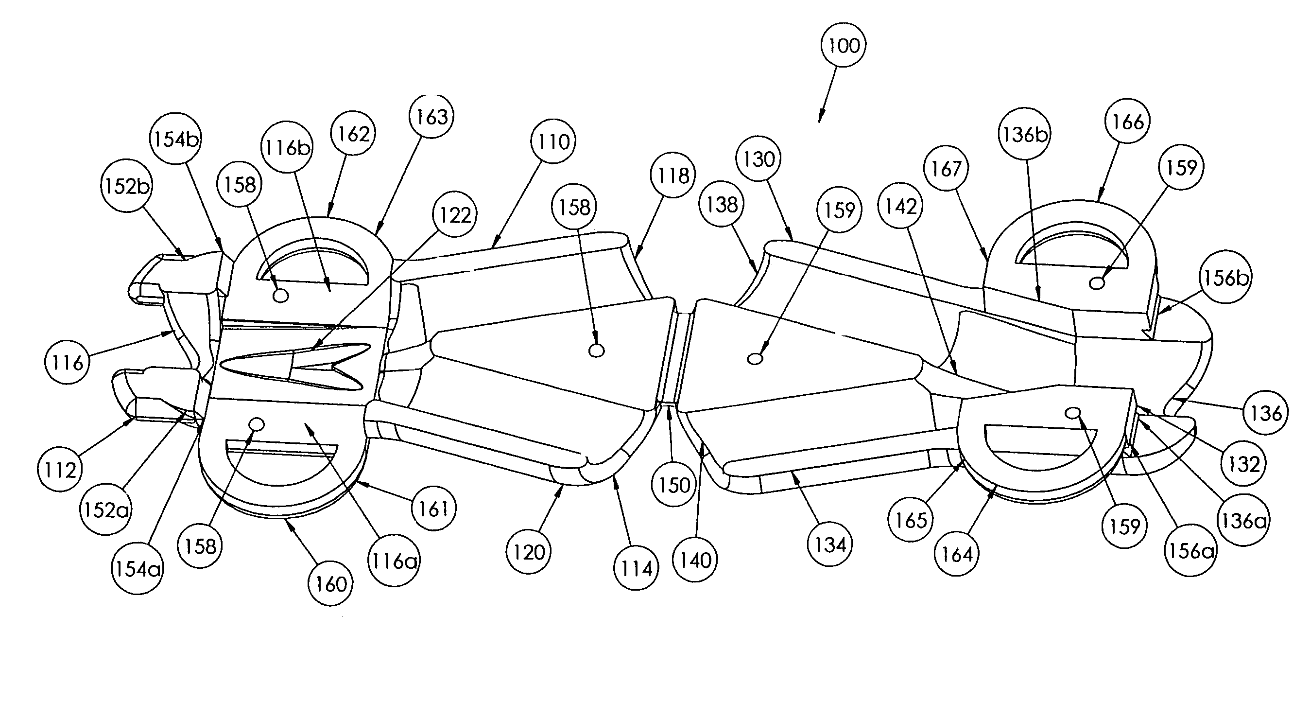
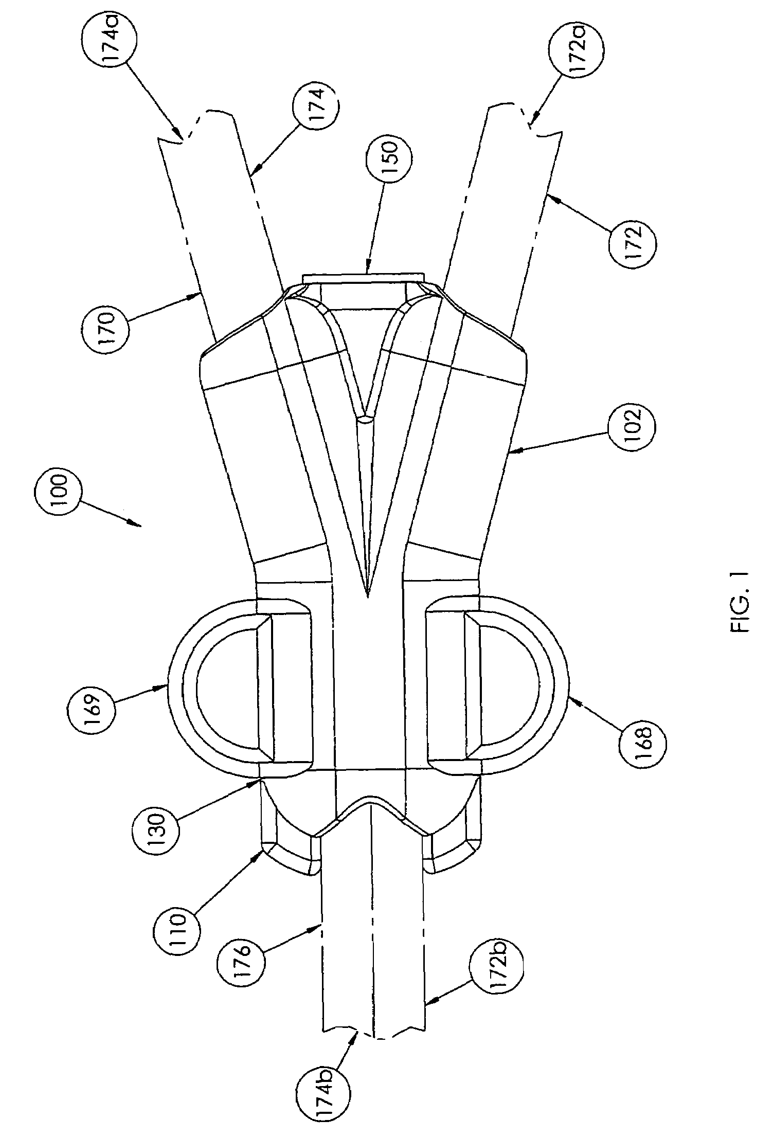
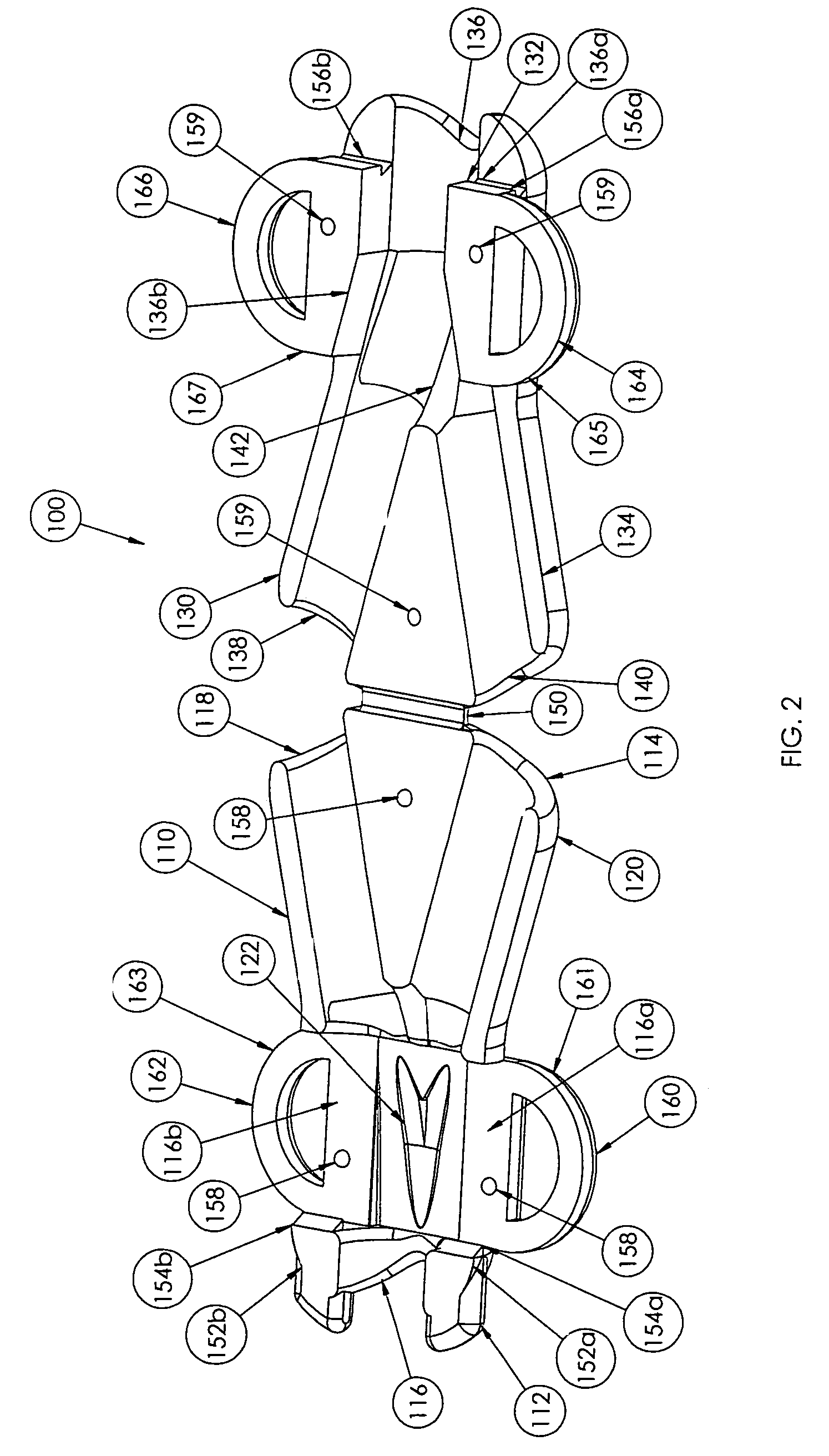
[0019]In the drawings, like numerals indicate like elements throughout. Certain terminology is used herein for convenience only and is not to be taken as a limitation on the present invention. The words “proximal” and “distal” refer to directions toward the right side and left side, respectively, of a catheter hub 100 shown in FIG. 1. The terminology includes the words above specifically mentioned, derivatives thereof, and words of similar import. The following describes a preferred embodiment of the invention. However, it should be understood, based on this disclosure, that the invention is not limited by the preferred embodiment described herein.

[0020]Referring now to FIG. 1, the catheter hub 100 is shown. The hub 100 may be used in multi-lumen catheters 170, such as the SPLIT STREAM™ catheter, manufactured by Medical Components, Inc. of Harleysville, Pa., which is disclosed in U.S. Provisional Patent Application Ser. No. 60 / 422,726, filed on Oct. 31, 2002, and U.S. Provisional Pa...


PUM


Abstract

A removable hub (100) for a catheter (170) including a lower portion (110) having a lower proximal end (114), a lower distal end (112), and a lower channel (116, 118, 120) extending between the lower proximal end and the lower distal end. The catheter hub (100) further includes an upper portion (130) having an upper proximal end (134), an upper distal end (132), and an upper channel (136,138,140) extending between the upper proximal end and the upper distal end. The catheter hub (100) further includes a hinge (150) connecting the lower portion and the upper portion and a lock (152a, 152b, 156a, 156b) for releasably securing the lower portion and the upper portion to each other, distal from the hinge. When the lower portion is releasably secured to the upper portion, the lower channel and the upper channel form a passageway (182, 184, 186).

Description

CROSS REFERENCE TO RELATED APPLICATIONS[0001]The present application claims priority from U.S. Provisional Patent Application Ser. No. 60 / 422,726, filed Oct. 31, 2002, and from U.S. Provisional Patent Application Ser. No. 60 / 423,002, filed Nov. 1, 2000.FIELD OF THE INVENTION[0002]The present invention relates to a catheter hub that can be slidably disposed along a portion of a length of a catheter assembly and / or removed from the catheter assembly.BACKGROUND OF THE INVENTION[0003]Catheters for the introduction or removal of fluids may be located in various venous locations and cavities throughout the body for introduction or removal of these fluids. Such catheterization may be performed by using a single catheter having multiple lumens. A typical example of a multiple lumen catheter is a dual lumen catheter in which one lumen introduces fluid and the other lumen removes fluid.[0004]Generally, to insert any catheter into a blood vessel, the vessel is identified by aspiration with a l...

Claims


Application Information

Patent Timeline
Patent Type & Authority Patents(United States)
IPC IPC(8): A61M25/00A61M25/18
CPCA61M25/0026A61M25/0029A61M25/0097A61M25/0023A61M25/0071A61M2025/0031A61M2025/0034A61M2025/0037A61M1/3661
Inventor RAULERSON, J. DANIEL
Owner MEDICAL COMPONENTS INC
Why Eureka
Try Eureka