The
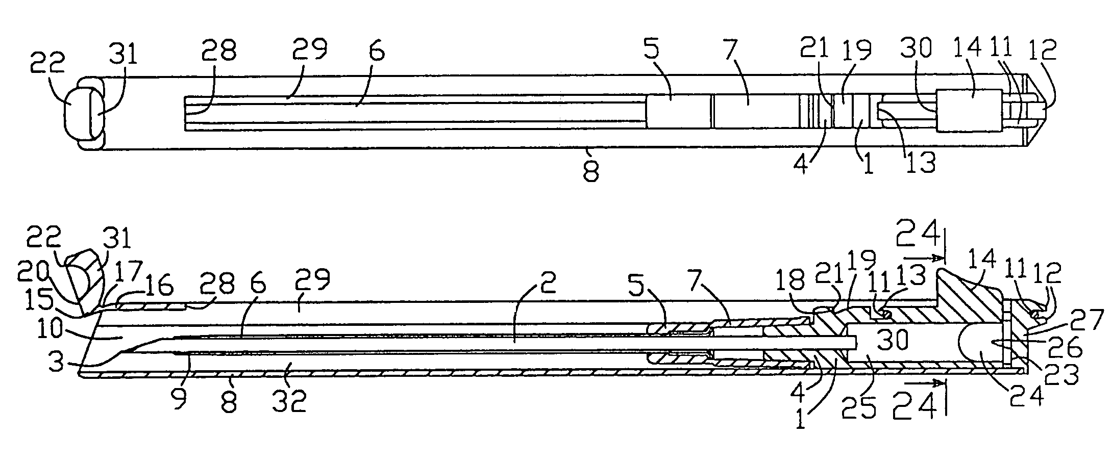
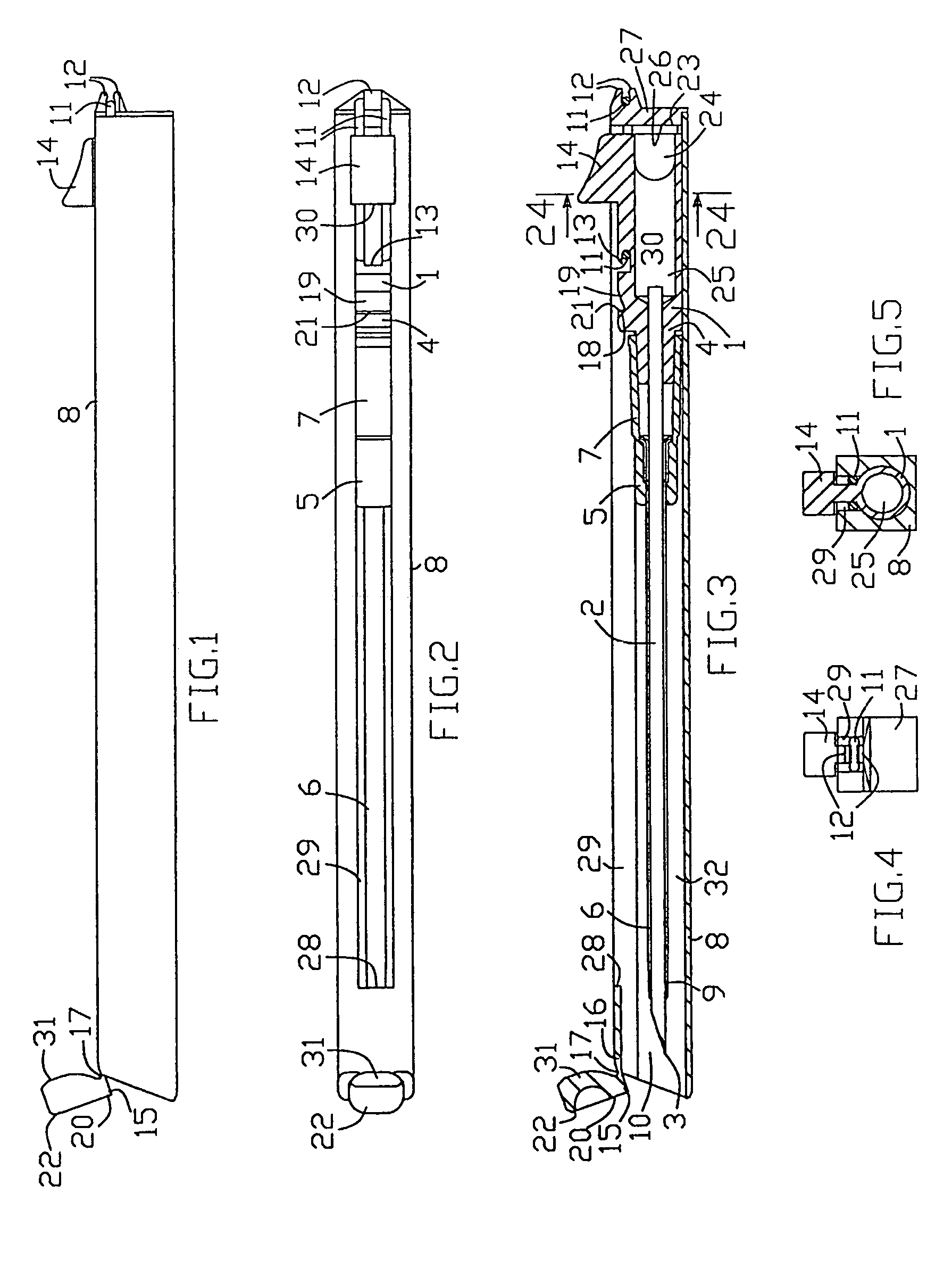
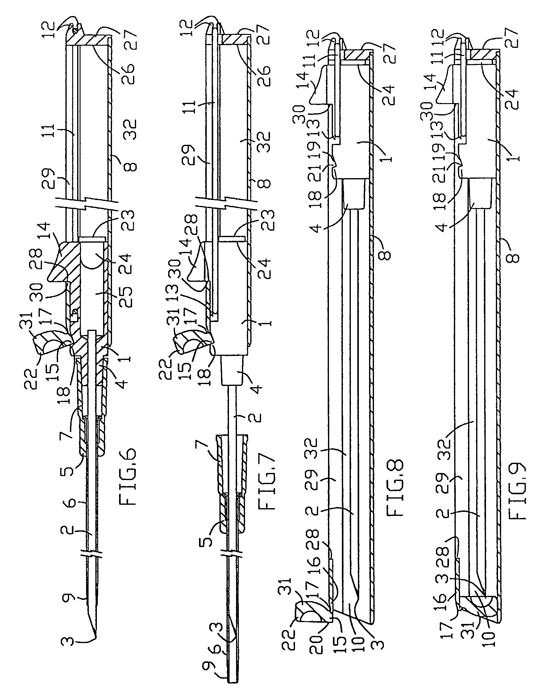
disadvantage of this device is its great length caused by the needle unit pusher, which, in the transport position, protrudes in proximal direction and thereby increases the device length.
Another
disadvantage is the absence of direct access to the
catheter hub in the duty ready position (see FIG. 5 of U.S. Pat. No. 4,988,339).
This impedes the control of the catheter by the user during catheter
insertion into the patient's
vein.
Another
disadvantage is the mutual disposition of the handle, the trigger member, and the pusher ruling out the possibility of the device control by the same hand, which holds the device.
Other part of the details, such as the handle,
syringe barrel, and
piston, include many slots and notches, which significantly complicate their fabrication.
As a result, the manufacturing cost of the device grows substantially.
Another disadvantage is the possibility of the needle unit exit from the protection position as a result of the action onto accessible pusher and fixation means.
The disadvantage of the apparatus is its increased length in the transport position due to the protrusion of the sheath tab distally from the hollow handle distal end as well as increased length of the needle caused by applying the needle hub part movable relative to the needle.
Another disadvantage is the unreliability of the retracting
mechanism based on the vacuum force, which demands very tight sealing.
Such sealing creates unstable friction between the needle hub and the hollow handle leading to jamming of the needle unit on the way to the protection position.
Another disadvantage is the increased outside
diameter of the hollow handle caused by the necessity to provide
free movement of the catheter hub inside the handle because the catheter hub is encircled with the sheath, having an inner thread, as well as a circular engagement recess on the hub movable part, which is located over the sheath.
Said
increased diameter impedes adjoining the catheter tightly to the patient's
skin creating catheterization problems.
Another disadvantage is the impossibility of converting the apparatus into the duty ready position by the same hand, which holds the apparatus.
Moreover, said conversion is complicated by the necessity to remove the sheath after transposing the catheter unit into the duty ready position.
Along with the above mentioned increased length that adds to
material consumption and fabrication complexity increasing the manufacturing cost of the apparatus.
One disadvantage is the low reliability of the vacuum retracting mechanism in connection with the friction between the needle hub and the hollow handle.
However, it should be taken into consideration that such a measure is effective only within reach of the trigger member, i. e. over the length of the short
distal portion, and cannot overcome a jam in the middle and proximal portions of the hollow handle.
The increased length and fabrication complexity add to
material consumption and, as a result, the manufacturing cost of the apparatus growths.
Thus, common disadvantages of the apparatuses with the transport position according to the prior art are:Large length leading to increased material consumption and transportation expenses.Inconvenience in operation due to the impossibility of controlling the device with one hand.Low reliability of automatic conversion of the apparatus from the duty ready position into the protection position.Relatively high manufacturing cost due to a large number of details, their complexity, and great material consumption.Limitation on the application of catheter various types, in particular the catheters with hub having a side port and wings for attaching the catheter to patient's
skin.Possibility of the needle unit displacement from the protection position leading to personnel infection by blood contaminated needle.


