Intravenous catheter inserting device

a catheter and intravenous technology, applied in the field of intravenous catheter inserting devices, can solve problems such as blood contamination, and achieve the effect of preventing contamination

Inactive Publication Date: 2005-07-26
SHUE MING JENG +2
View PDF6 Cites 67 Cited by
  • Summary
  • Abstract
  • Description
  • Claims
  • Application Information

AI Technical Summary

Benefits of technology

[0006]The object of the present invention is to provide an intravenous catheter inserting device which can prevent accidental, inadvertent contact with a needle cannula after use, and which can prevent contamination of that was drawn with the use of the same.

Problems solved by technology

Moreover, blood contamination may occur during connection of the catheter hub 13 to the transfusion member or the empty barrel.

Method used


Image

  • Intravenous catheter inserting device
  • Intravenous catheter inserting device
  • Intravenous catheter inserting device

Examples


Embodiment Construction

[0030]Before the present invention is described in greater detail, it should be noted that same reference numerals have been used to denote like elements throughout the specification.

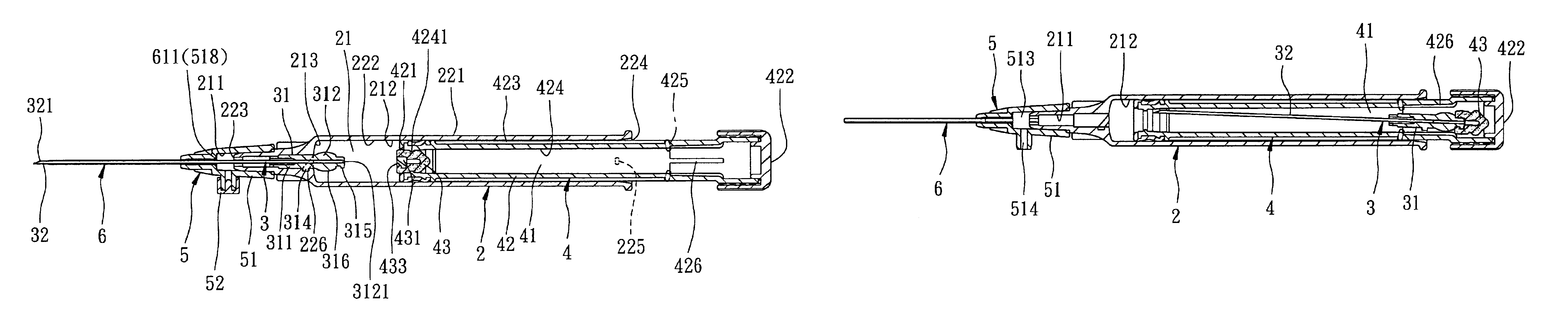
[0031]Referring to FIGS. 3 and 4, the first preferred embodiment of an intravenous catheter inserting device according to the present invention is shown to comprise a catheter hub 5, a tubular catheter 6, a barrel 2, a needle assembly 3, and a plunger 4.

[0032]The catheter hub 5 includes a surrounding tip wall 512, a sleeve wall 511 which is opposite to the surrounding tip wall 512 along a first axis, and an intermediate tubular wall 51 which is interposed between the surrounding tip wall 512 and the sleeve wall 511.

[0033]The surrounding tip wall 512 surrounds the first axis, and confines a through hole 516 which extends along the first axis. The sleeve wall 511 has an inner sleeve wall surface which surrounds the first axis and which confines an insert hole 517 larger than the through hole 516. The inte...


PUM


Abstract

An intravenous catheter inserting device includes a catheter hub engaging an open forward end of a barrel and having a duct that communicates with a passage of the barrel. A tubular catheter is disposed to communicate with the duct, and permits a needle cannula to pass therethrough. A plunger is received in the passage and extends rearwardly of the barrel so as to be manually operable. The plunger has a cavity containing fluid at a reduced pressure, and is coupled with the needle cannula within the passage such that the needle cannula can be retracted into the cavity due to a pressure difference between the ambient air and the reduced pressure.

Description

BACKGROUND OF THE INVENTION[0001]1. Field of the Invention[0002]This invention relates to an intravenous catheter inserting device, more particularly to an intravenous catheter inserting device which enables a needle cannula to be retracted within a plunger cavity having a reduced pressure therein.[0003]2. Description of the Related Art[0004]Intravenous catheter inserting devices are generally used to administer medication fluid into or draw blood from a patient's vein. Referring to FIGS. 1 and 2, a conventional intravenous catheter inserting device 1 is shown to include a tubular needle seat 11 with a hub end 111, a needle cannula 12 secured to the hub end 111, a catheter hub 13 sleeved on the needle seat 11, and a flexible tubular catheter 14 secured to the catheter hub 13. In use, the catheter 14 and the needle cannula 12 are inserted into the patient's vein by a health care worker by piercing the patient's vein with a sharp tip of the needle cannula 12 which projects outwardly o...

Claims


Application Information

Patent Timeline
Patent Type & Authority Patents(United States)
IPC IPC(8): A61B5/15A61M5/32A61M5/315A61M5/50A61M25/06
CPCA61B5/1411A61M25/0606A61M5/3232A61M2005/3231A61M5/508A61B5/15003A61B5/150389A61B5/150519A61B5/150641A61B5/150732A61B5/153
Inventor SHUE, MING-JENGSHUE, PHILLIPHUANG, DEBORAH
Owner SHUE MING JENG
Why Eureka
Try Eureka