

Catheter-advancement actuated needle retraction system
a needle retraction and advanced technology, applied in the direction of catheters, guide needles, infusion needles, etc., can solve the problem of contamination of needlesticks with needlesticks
- Summary
- Abstract
- Description
- Claims
- Application Information
AI Technical Summary
Benefits of technology
Problems solved by technology
Method used
Image

Examples
second embodiment
[0043]latch actuator 260 is shown in FIGS. 6 through 8. In that embodiment, latch actuator 260 comprises a wire formed into two longitudinally extending rails 269 and a push off tab 268. Alternatively, latch actuator 260 could include only one longitudinally extending rail 269. Push off tab 268 is formed such that it snaps over catheter hub 11 and can be easily removed from catheter hub 11 once catheter 10 is properly placed in a patient's vein. Longitudinally extending rails 269 extend into barrel 230 in chambers 231 and 232 so that at least one of the longitudinally extending rails 269 will interact with latch 250 to disengage latch 250 from needle hub 221 to allow needle 20 to retract into barrel 230.
[0044]In the second embodiment of this invention, latch 250 pivots about point 251 in a cantilever fashion and is biased away from needle hub 221. Latch 250 inches an enlarged foot 252 than engages needle hub 221. Foot 252 is held in slot 225 of needle hub 221 by one of the longitudi...
third embodiment
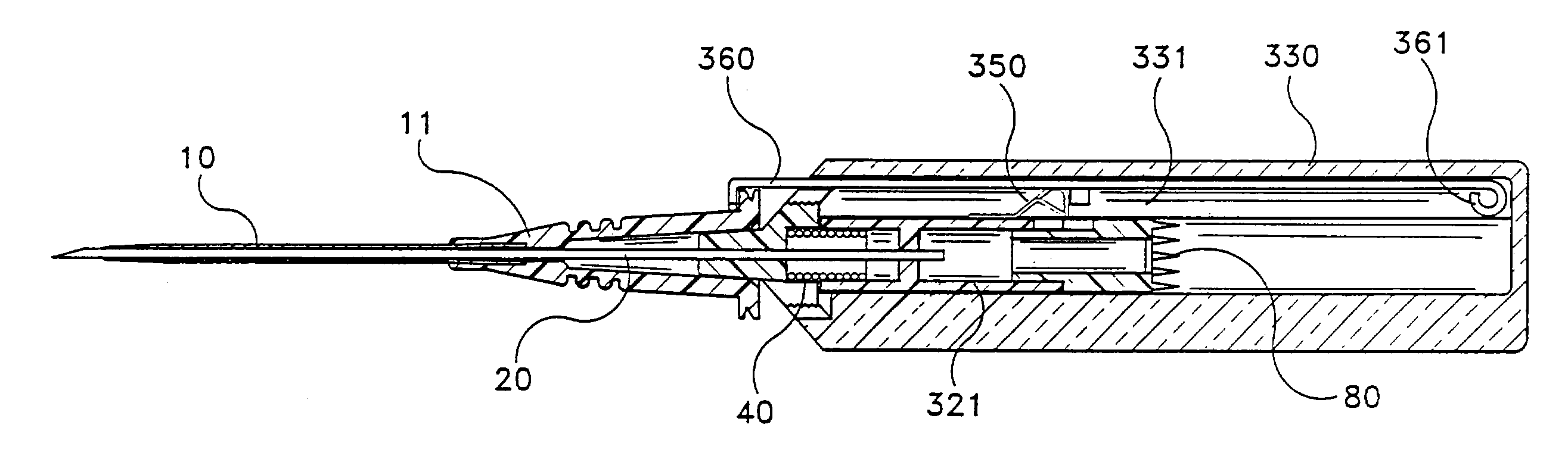
[0047]In this invention shown in FIGS. 9 through 14, latch 350 is affixed to the outer surface of needle hub 321. Latch 350 has an upwardly extending body 353 that is biased away from needle hub 321. Latch 350 also has a portion which descends from body 353 in a gradual ramp 354 and another portion which ends in abutments 355. These abutments 355 engage with shoulders 331 formed in the inner wall of barrel 330. Shoulders 331 are shown in FIGS. 11 and 12 and are in phantom in FIG. 13.
[0048]Latch actuator 360 is formed with a pigtail 361 at its proximal end. Needle hub 321 is oriented in barrel 330 so that latch actuator 360 extends over ramp 354 of latch 350. As needle 20 is removed from catheter 10, latch actuator 360 passes over ramp 354. When pigtail 361 passes over ramp 354, latch 350 is urged toward needle hub 321 so that abutments 355 disengage from shoulders 331. This allows spring 40 to urge needle hub 321 away from the distal wall of barrel 330.
[0049]The proximal end of need...
fifth embodiment
[0051]In this invention, shown in FIGS. 17 through 24, a camming rod 569 is used to move a keylatch 550 out of engagement with needle hub 521. Keylatch 550 includes a keyhole 555 therein having a larger portion 555a and a smaller portion 555b. Keylatch 550 rides along rail 595 of camming rod 569. Rail 595 is arranged to allow either larger hole 555a or smaller hole 555b to be aligned with the longitudinal axis of camming rod 569.
[0052]Camming rod 569 rides along the bottom of barrel 530 so that push off tab 568 is either adjacent to the distal end of barrel 530, as shown in FIGS. 17 and 20, or is removed therefrom as shown in FIG. 21. The distal end of camming rod 269 includes bulbous distal tips 501 which function in the same manner as the automatic release mechanism shown in FIG. 15.
[0053]Keylatch 550 is disposed inside barrel 530 about needle hub 521. When camming rod 569 is in the position shown in FIGS. 17 and 20, smaller hole 555b engages needle hub 521 to hold it adjacent to ...
PUM
 Abstract
Description
Claims
Application Information