Indoor unit for air conditioner

a technology for indoor units and air conditioners, applied in the field of indoor units for air conditioners, can solve the problems of inability to properly correspond, difficulty in collecting condensed water, and change in the width and length of the place where the indoor unit is located, so as to reduce the manufacturing cost of the indoor unit, improve the use convenience, and actively respond to consumer tastes

Inactive Publication Date: 2007-09-04
LG ELECTRONICS INC
View PDF13 Cites 24 Cited by
  • Summary
  • Abstract
  • Description
  • Claims
  • Application Information

AI Technical Summary

Benefits of technology

[0014]It is another object of the present invention to provide an indoor unit for an air conditioner in which when the installation direction of the indoor unit is changed, condensed water can be rapidly drained regardless of the moving direction of the condensed water due to gravity. In other words, like when the indoor unit is installed in a straight standing state, a standing state on its head, or a lying state, although the indoor unit is installed in any direction, the indoor unit allows the condensed water essentially generated during operation of the indoor heat exchanger to be completely drained to the outside, thereby capable of actively responding to consumer's taste.
[0015]It is a further object to provide an indoor unit for an air conditioner that allows the indoor unit to be installed regardless of the installation direction through a simply change of the shape and construction without complicated change of the construction, thereby reducing the manufacturing costs of the indoor unit and enhancing the use convenience.
[0021]According to the present invention, drain problem of condensed water can be solved regardless of arranged state and mounted state of the indoor unit.

Problems solved by technology

That is, when it is necessary to install the indoor unit in a standing state on its head depending on a change in the place where the indoor unit is mounted, and a change in the width and length of the place where the indoor unit is mounted, proper correspondence is impossible.
In detail, when the inner door is mounted on the relatively high ceiling or the like in a standing state on its head, drain pan is positioned at the uppermost place of the indoor unit and indoor heat exchanger is positioned below the drain pan, which results in difficulty in collecting condensed water.
Accordingly, a user fails to selectively install the indoor unit in a standing state on its head or a standing straight state.

Method used


Image

  • Indoor unit for air conditioner
  • Indoor unit for air conditioner
  • Indoor unit for air conditioner

Examples


Embodiment Construction

[0032]Reference will now be made in detail to the preferred embodiments of the present invention, examples of which are illustrated in the accompanying drawings. It will be apparent to those skilled in the art that various modifications and variations can be made in the present invention. Thus, it is intended that the present invention covers the modifications and variations of this invention provided they come within the scope of the appended claims and their equivalents.

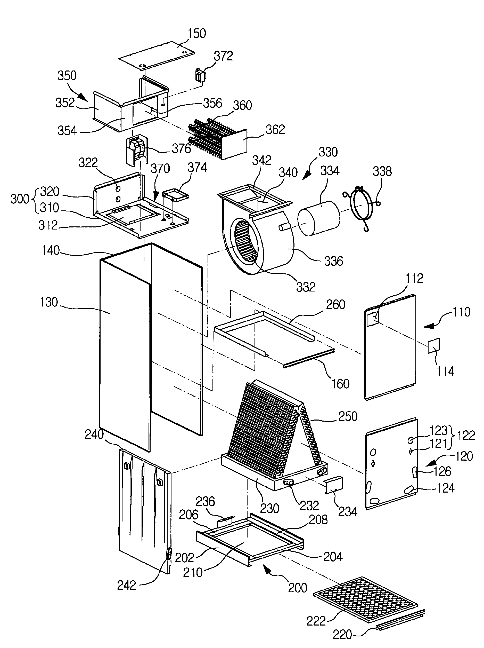
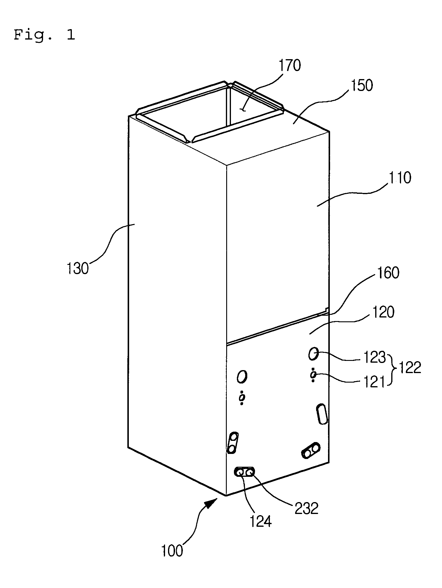
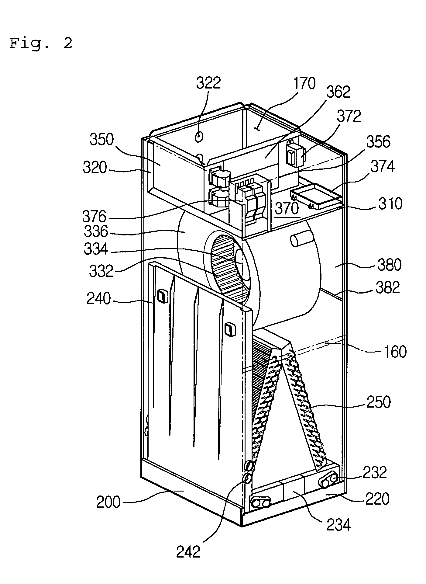
[0033]FIG. 1 is a perspective view illustrating an appearance of an indoor unit for an air conditioner according to a preferred embodiment of the present invention, FIG. 2 is an inner perspective view of an indoor unit for an air conditioner for an air conditioner according to an embodiment of the present invention, and FIG. 3 is a disassembled perspective view of an indoor unit for an air conditioner according to the present invention.

[0034]Referring to FIGS. 1 to 3, an indoor unit 100 is approximately shaped in a...


PUM


Abstract

Disclosed is an indoor unit for an air conditioner to solve drain problem of condensed water. The indoor unit includes: a lower frame provided with a suction inlet through which exterior air is inhaled; a middle frame spaced upward apart from the lower frame by a predetermined distance; an indoor heat exchanger for performing heat exchange; and a drain pan for collecting and draining condensed water generated in the indoor heat exchanger, the drain pan being mounted selectively on the lower frame or the middle frame.

Description

BACKGROUND OF THE INVENTION[0001]1. Field of the Invention[0002]The present invention relates to an air conditioner, and more particularly, to an indoor unit for an air conditioner in which the indoor unit is installed standing on its head with ease. Further, this invention is directed toward an indoor unit for an air conditioner in which drain problem of condensed water generated in the course of heat exchange in the indoor unit is solved to thereby enhance the use efficiency.[0003]2. Description of the Related Art[0004]In general, air conditioner is a cooling / heating apparatus installed in an indoor space such as office, home or the like, for cooling or heating the indoor space. Also, air conditioner is an apparatus for changing air status through a series of cooling cycle made by compressor, condenser, expander and evaporator.[0005]The air conditioner includes an outdoor unit installed at an outdoor space and an indoor unit installed at an inner space of a building. The outdoor u...

Claims


Application Information

Patent Timeline
Patent Type & Authority Patents(United States)
IPC IPC(8): F25D21/14F24F1/0097F24F3/06F24F13/22F24F13/24
CPCF24F1/0007F24F13/24F24F2001/004F24F2003/1678F24F1/0022F24F1/005F24F8/28F24F1/0097
Inventor EOM, NAM SEOBJEON, JEONG YONG
Owner LG ELECTRONICS INC
Why Eureka
Try Eureka