Processing apparatus with sealing mechanism

a sealing mechanism and processing apparatus technology, applied in the direction of liquid handling, packaging goods, cleaning using liquids, etc., can solve the problems of short life of sealing members, breakage of sealing members, and leakage of processing fluid or vapor resulting from using high-temperature liquid or gas as processing liquid outside, so as to improve sealing capability and increase life. the effect of the life span

Inactive Publication Date: 2004-03-02
TOKYO ELECTRON LTD
View PDF37 Cites 19 Cited by
  • Summary
  • Abstract
  • Description
  • Claims
  • Application Information

AI Technical Summary

Benefits of technology

is to provide a processing apparatus with sealing mechanism, which is ...

Problems solved by technology

That is, if the sealing part is damaged or does not give full sealing effect for some reason or other, then a problem may arise in that the processing fluid or vapor resulting from using high-temperature liquid or gas as the processing liquid leaks outside.
With the necessity of sealing a part operating at both times of sealing and non-sealing, it has been also studied to expand the sealing member by using pressurized fluid at the sealing; nevertheless there still exists a problem of the sealing member's short life span and also a necessity of measure against the sealing member's breakage.
Further, since the use of high-temperature liquid or gas as the processing fluid causes the sealing member to be exposed to the high-temperature atmosphere, the sealing member has to be made from heat-resistant material, restricting the scope of materials for the sealing member.
In the conventional sealin...

Method used


Image

  • Processing apparatus with sealing mechanism
  • Processing apparatus with sealing mechanism
  • Processing apparatus with sealing mechanism

Examples


first embodiment

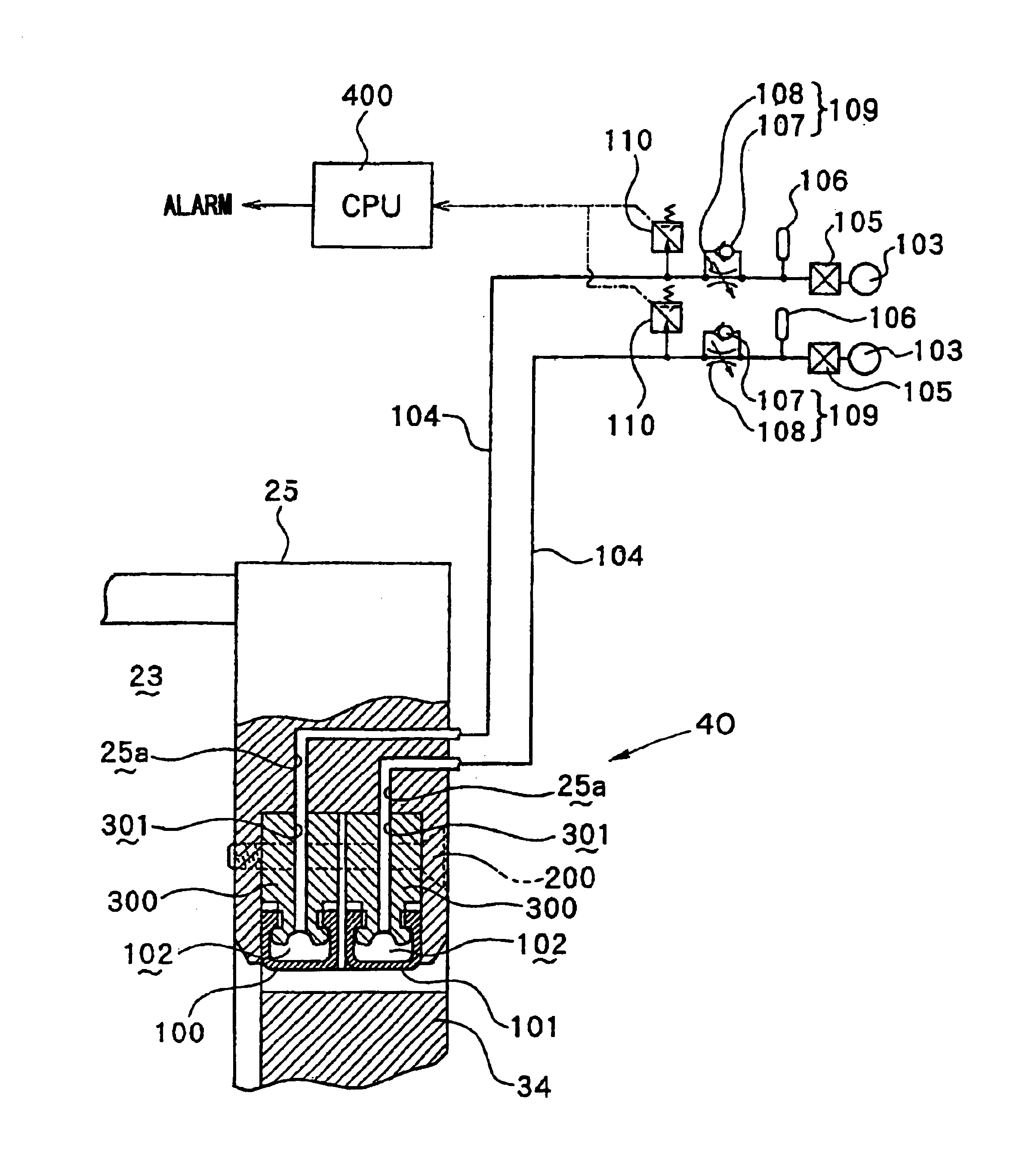
In this way, through the closing switching valve 140 and the pressure-detecting switch 110, the air source 141 is connected with the hollow part 102 of the deformable hollow packing 130 having a substantial M-shaped section at the non-compressed state. Under condition that the inner cylinder 25 is in the standby mode or moving, when the position of the closing switching valve 140 is shifted to its exhausting side, the supply of pressurized-air from the air source 141 is stopped to deform the deformable hollow packing 130 to have the substantial M-shaped section, realizing the non-contact condition between the deformable hollow packing 130 and the inner cylinder 25 (see FIG. 9A). Under condition that the inner cylinder 25 has been moved to its usable position, when the position of the closing switching valve 140 is shifted to its compressing side, the pressurized air from the air source 141 is fed to the hollow part 102 of the deformable hollow packing 130 for its convex shape, so th...

fourth embodiment

Thus, according to the sealing mechanism 40C of the fourth embodiment, since the small supply of compressed air from the air source 141 allows the deformable hollow packing 130 to be deformed convexly to maintain the sealing condition, it is possible to realize the ensured sealing condition by the hollow packing 130 in a single layer. While, when exhausting air in the hollow part 102, the deformable hollow packing 130 is deformed so as to have the substantial M-shaped section, thereby ensuring the non-contact between the packing and the first stationary wall 34. Thus, owing to the elimination of possibility that the deformable hollow packing 130 comes in frictional contact with the first stationary wall 34 (closing means) during moving the inner cylinder 25, it is possible to plan to prolong the life of the deformable hollow packing 130.

Although the above description relates to the single arrangement of the deformable hollow packing 130, the double arrangement of the packings 130 on...

second embodiment

In the shown double arrangement of the deformable hollow packings 130 of FIG. 10, it is preferable to connect the exhausting means 112 with the interval between the deformable hollow packings 130 through the gas sensor 111 (leakage detecting means), as similar to the Note, the gas sensor 111 is electrically connected with the CPU 400, allowing the deterioration in sealing effect of the packings 130 to be detected (or monitored).

Note, since the other parts of the fourth embodiment are identical to those of the first and second embodiments, these elements are respectively indicated with the same reference numerals of those elements of these embodiments and their descriptions are eliminated.

Also noted in the fourth embodiment, the deformable hollow packing(s) 130 in the non-compressed (non-sealing) state is formed with substantial-M shaped section: nevertheless the cross section may be modified to another form, for example, substantial U-shaped configuration.

Although the fourth embodi...


PUM

PropertyMeasurementUnit
Pressureaaaaaaaaaa
Flexibilityaaaaaaaaaa

Abstract

A processing apparatus includes an inner cylinder 25 (a processing chamber 23) accommodated in a carrying unit for carrying an object to be processed and further seals up the object with the inner cylinder 25 or a first stationary wall 34 to process the object in contact with processing fluid. In this processing apparatus with sealing mechanism, flexible hollow packings 100, 101 are arranged doubly in either the inner cylinder 25 or the first stationary wall 34, at its occluded part with the first stationary wall 34 and the inner cylinder 25. The hollow packings 100, 101 have their hollow parts 102 connected with respective pressurized-air sources 103 through pressure-detecting switches 110 and closing valves 105. By expanding or contracting the hollow packings 100, 101, the operation of the apparatus is switched in between its sealing state and non-sealing state. With this arrangement, it is possible to improve the sealing capability and prolong the life of the mechanism.

Description

BACKGROUND OF THE INVENTION1. Technical Field of the InventionThis invention relates to a processing apparatus with sealing mechanism, more particularly, the processing apparatus with sealing mechanism, which accommodates objects to be processed, such as semiconductor wafers and LCD glass substrates, in a processing chamber having a sealed atmosphere and which makes the objects in contact with processing fluid (e.g. chemical liquid, rinsing liquid), drying fluid, reactive gas or the like.2. Description of the Related ArtGenerally in the manufacturing process of semiconductor devices and the LCD manufacturing process, there is widely adopted, as one processing apparatus with sealing mechanism, a cleaning and drying apparatus that uses the processing fluid, such as processing liquid and gas, in order to remove resist sticking to the object to be processed (e.g. semiconductor wafer, LCD glass) and residue (polymer etc.) sticking thereto after the drying process. Note, the above object ...

Claims


Application Information

Patent Timeline
IPC IPC(8): H01L21/00
CPCH01L21/67028Y10T29/41Y10S134/902H01L21/00
Inventor KAMIKAWA, YUJIEGASHIRA, KOJI
Owner TOKYO ELECTRON LTD
Why Eureka
Try Eureka