Electrical junction box

a technology of electrical junction box and box body, which is applied in the direction of electric/fluid circuit, electrical apparatus, vehicle components, etc., can solve the problems of inability to meet the demand for the reduction in the size of the electrical junction box, the size of the electrical junction box is inevitably increased, etc., to avoid the increase in the size the effect of suppressing the expansion of the electrical junction box

Active Publication Date: 2017-07-20
SUMITOMO WIRING SYST LTD
View PDF1 Cites 19 Cited by
  • Summary
  • Abstract
  • Description
  • Claims
  • Application Information

AI Technical Summary

Benefits of technology

[0013]With this aspect, when the upper cover is rotated and fitted to the box body, in at least a portion of the region other than the region located on the one end side where the interference between the inner wall of the upper cover and the outer wall of the box body is not problematic, the position of the projecting end surface of the inner wall of the upper cover is set to be lower than the position of the projecting end surface of the outer wall of the box body. In this region, the inner wall of the upper cover can be fitted between the outer wall and the inner wall in the double wall of the box body, and therefore, the upper opening portion of the box body can be stably covered with the upper cover.
[0014]With the electrical junction box according to the present design, in the state in which the upper cover is attached to the box body, on the one end sides of the box body and the upper cover, the position of the projecting end surface of the inner wall of the upper cover is set to be as high as or higher than the position of the projecting end surface of the outer wall of the box body. Accordingly, when the upper cover is rotated with the engaging portion of the upper cover serving as the rotation center, the interference between the one end of the inner wall of the upp

Problems solved by technology

With such a conventional structure, the size of the electrical junction box is inevitably increased, and t

Method used


Image

  • Electrical junction box
  • Electrical junction box
  • Electrical junction box

Examples


Embodiment Construction

[0023]Hereinafter, an embodiment of the present invention will be described with reference to the drawings.

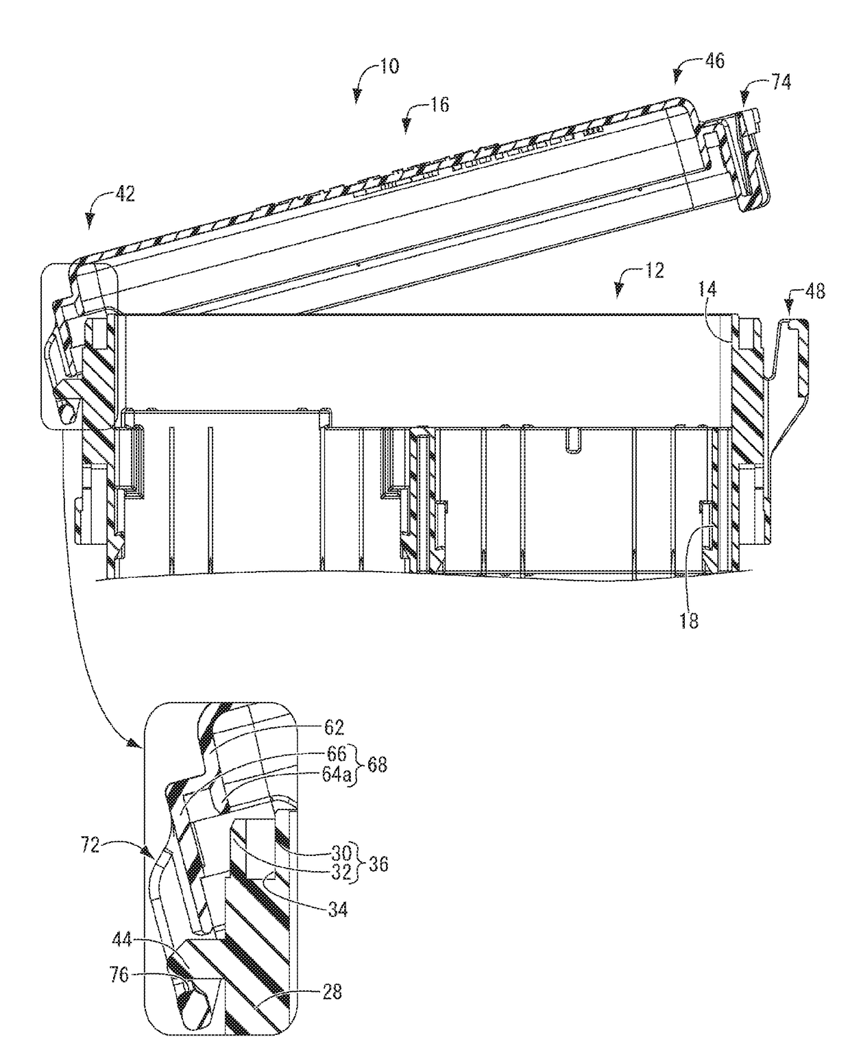
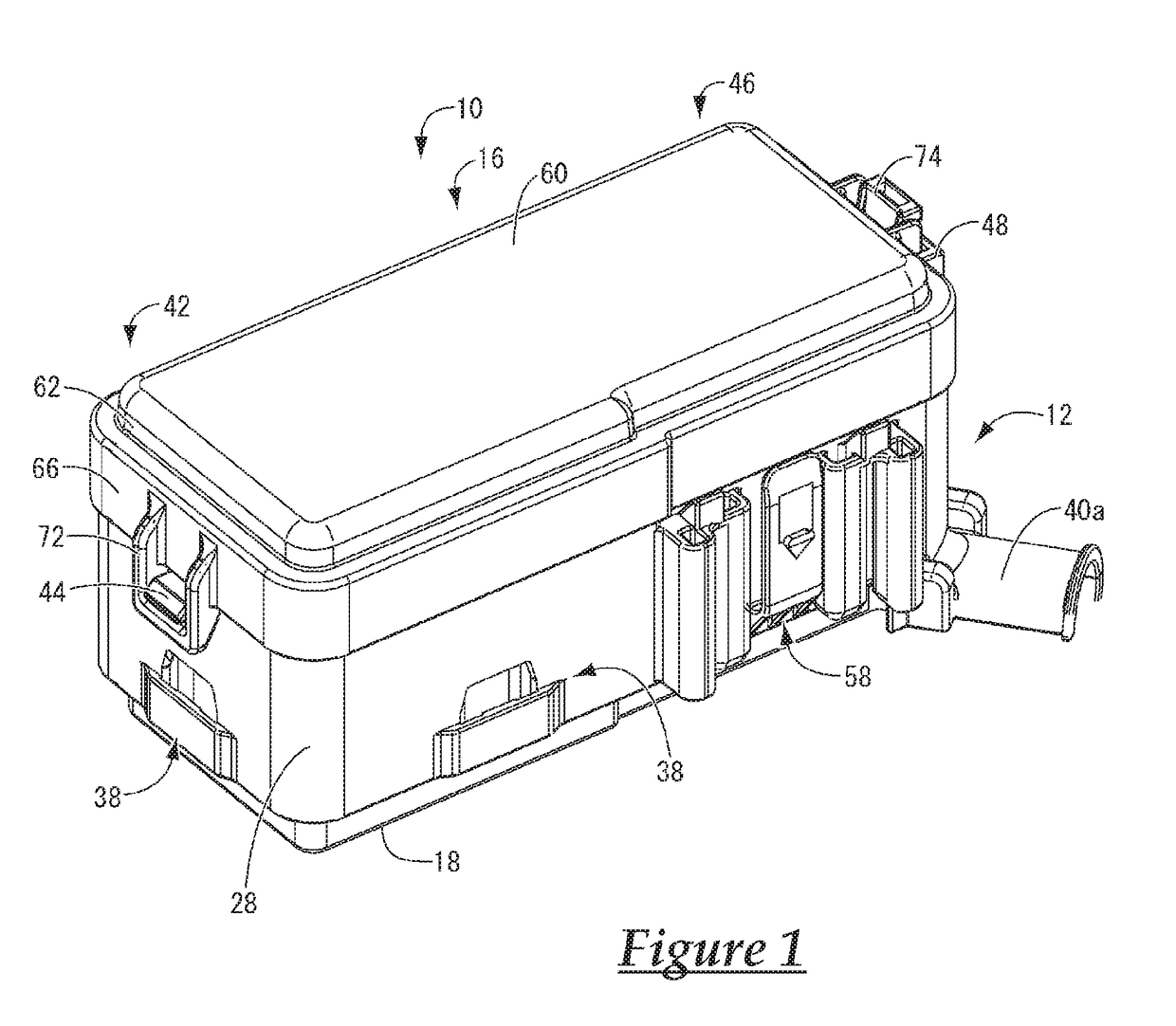
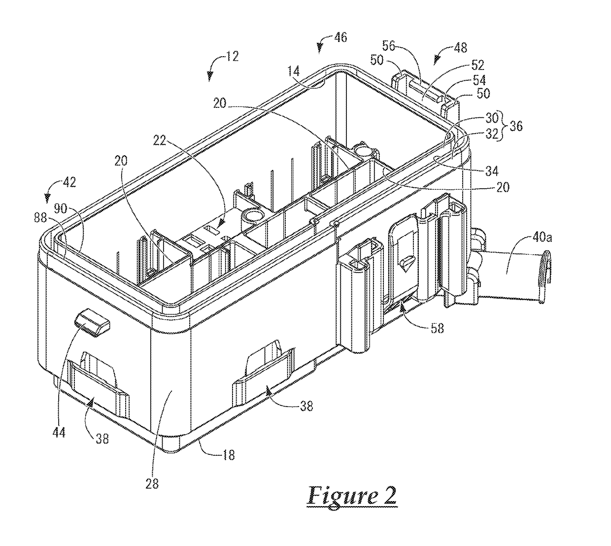
[0024]FIGS. 1 to 8 show an electrical junction box 10 according to an embodiment of the present design. The electrical junction box 10 is arranged at an appropriate position in a vehicle (not shown) such as an automobile and has a function for distributing electric power supplied by a battery to vehicle-mounted electrical components such as a motor and a lamp. It should be noted that the electrical junction box 10 is mounted in a vehicle such that the up-down direction in FIG. 1 corresponds to the vertical direction. In the description below, unless otherwise stated, the up-down direction refers to the up-down direction in FIG. 1, the longitudinal direction and the front-rear direction refer to the left-right direction in FIG. 4, and the width direction refers to the up-down direction in FIG. 4.

[0025]More specifically, the electrical junction box 10 is configured to include a b...


PUM


Abstract

An electrical junction box in which the interference between an inner wall of a rotating upper cover and an outer wall of a box body can be more reliably prevented and a waterproof property can be secured, while also meeting the demand for reduction in size of the electrical junction box. In a state in which an upper cover is attached to a box body, on one end side of the box body and one end side of the upper cover, an outer wall of the box body is located on an inner side with respect to an outer wall of the upper cover, an inner wall of the upper cover is located on an inner side with respect to the outer wall of the box body, and an inner wall of the box body is located on an inner side with respect to the inner wall of the upper cover.

Description

CROSS REFERENCE TO RELATED APPLICATIONS[0001]This application claims the priority of Japanese patent application JP2014-150181 filed on Jul. 23, 2014, the entire contents of which are incorporated herein.TECHNICAL FIELD[0002]The present invention relates to an electrical junction box to be mounted in an automobile or the like, and particularly to an electrical junction box having a waterproof structure with which infiltration of water from the outside is prevented.BACKGROUND ART[0003]Conventionally, electrical junction boxes to be mounted in automobiles and the like are configured to include a box body that has a peripheral wall formed in a frame shape and keeps electric parts such as a relay, a fuse, and an electric wire installed inside the peripheral wall, and lid bodies such as an upper cover and a lower cover with which opening portions on the upper and lower sides of the box body are covered. For example, electrical junction boxes are configured as disclosed in JP 2013-34320A ...

Claims


Application Information

Patent Timeline
IPC IPC(8): H02G3/14H02G3/08
CPCH02G3/14H02G3/088H02G3/081B60R16/0238
Inventor SHIRAKI, TAKASHI
Owner SUMITOMO WIRING SYST LTD
Why Eureka
Try Eureka