Method for humerus retraction

a humerus and lumbar joint technology, applied in the field of surgical retraction, can solve the problems of pain when the shoulder joint is articulated, limited access to the surgical site, and the surgical procedure can become quite physically taxing on the surgeon or surgeons performing the surgery

Inactive Publication Date: 2007-09-04
MINNESOTA SCI
View PDF16 Cites 17 Cited by
  • Summary
  • Abstract
  • Description
  • Claims
  • Application Information

AI Technical Summary

Problems solved by technology

The deterioration causes either the humeral ball, the glenoid cavity or both the humeral ball and the glenoid cavity become rough which results in pain when the shoulder joint is articulated.
Because of the relatively small size of the incision and the surgical site being on one side of the body, access to the surgical site is limited.
Due to the multiple dislocations and insertions of the humeral ball into the glenoid cavity, as well as retracting the humerus, the surgical procedure can become quite physically taxing on the surgeon or surgeons performing it.
Depending on the size of the patient, the strenuous activity can lead to fatigue and contribute to surgical error.
Additionally, the repeated movement of the arm can cause nerve damage if it is not done precisely and with minimal adjustment.
Often, the surgeon holding the arm, relaxes or becomes fatigued and allows the arm to move, requiring that the arm be readjusted.
The movement can cause the arm to pinch or rub nerves or muscle tissue, possibly causing damage.

Method used


Image

  • Method for humerus retraction
  • Method for humerus retraction
  • Method for humerus retraction

Examples


Embodiment Construction

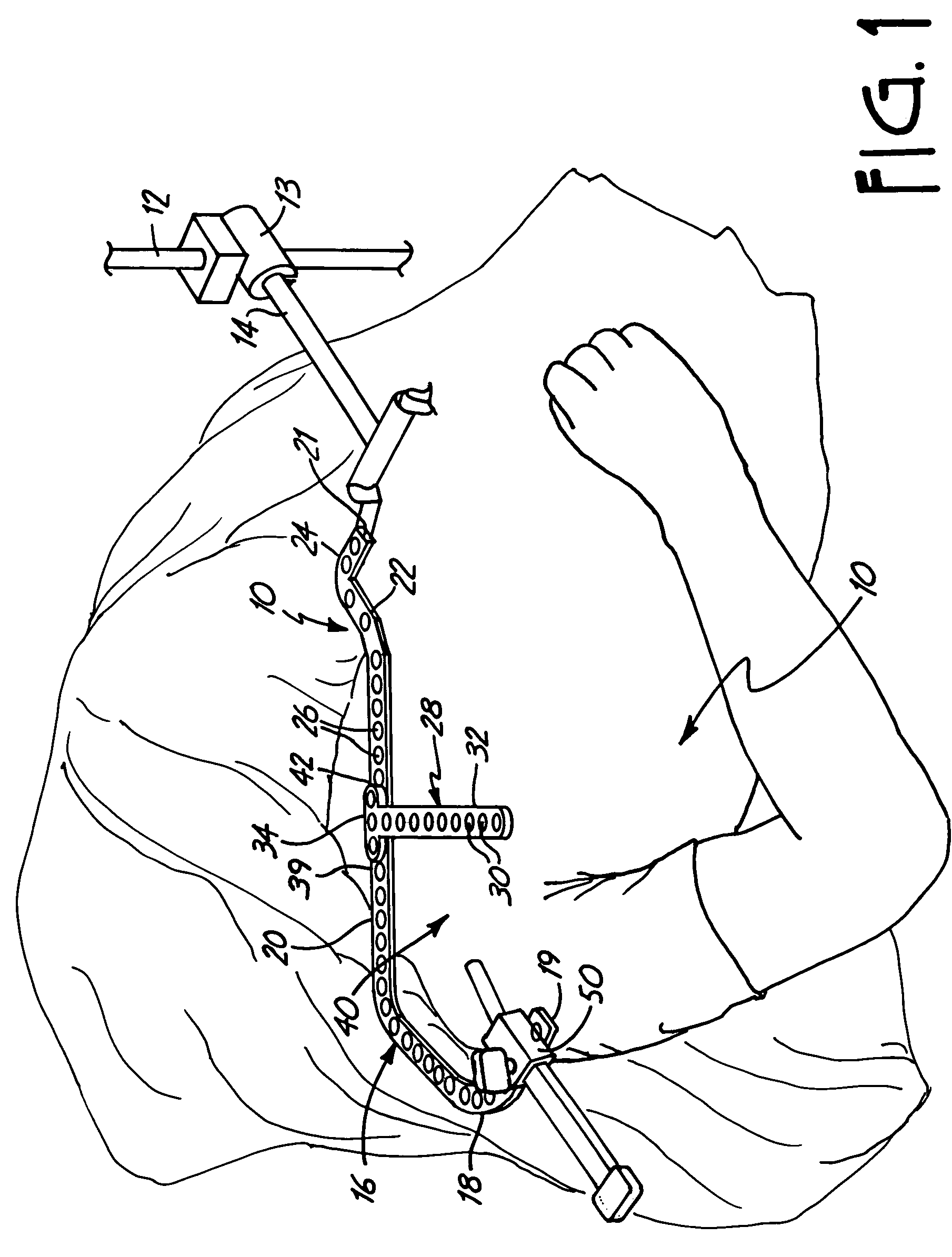
[0020]The present invention relates to a method for retracting the upper arm or humerus bone during a shoulder surgery as generally illustrated in FIG. 1 at 10. In preparation for a shoulder replacement surgery, a height of a generally J-shaped member 16 is adjusted by clamping the support member 14 in a selected position on a retractor support apparatus 12 with a clamp 13.

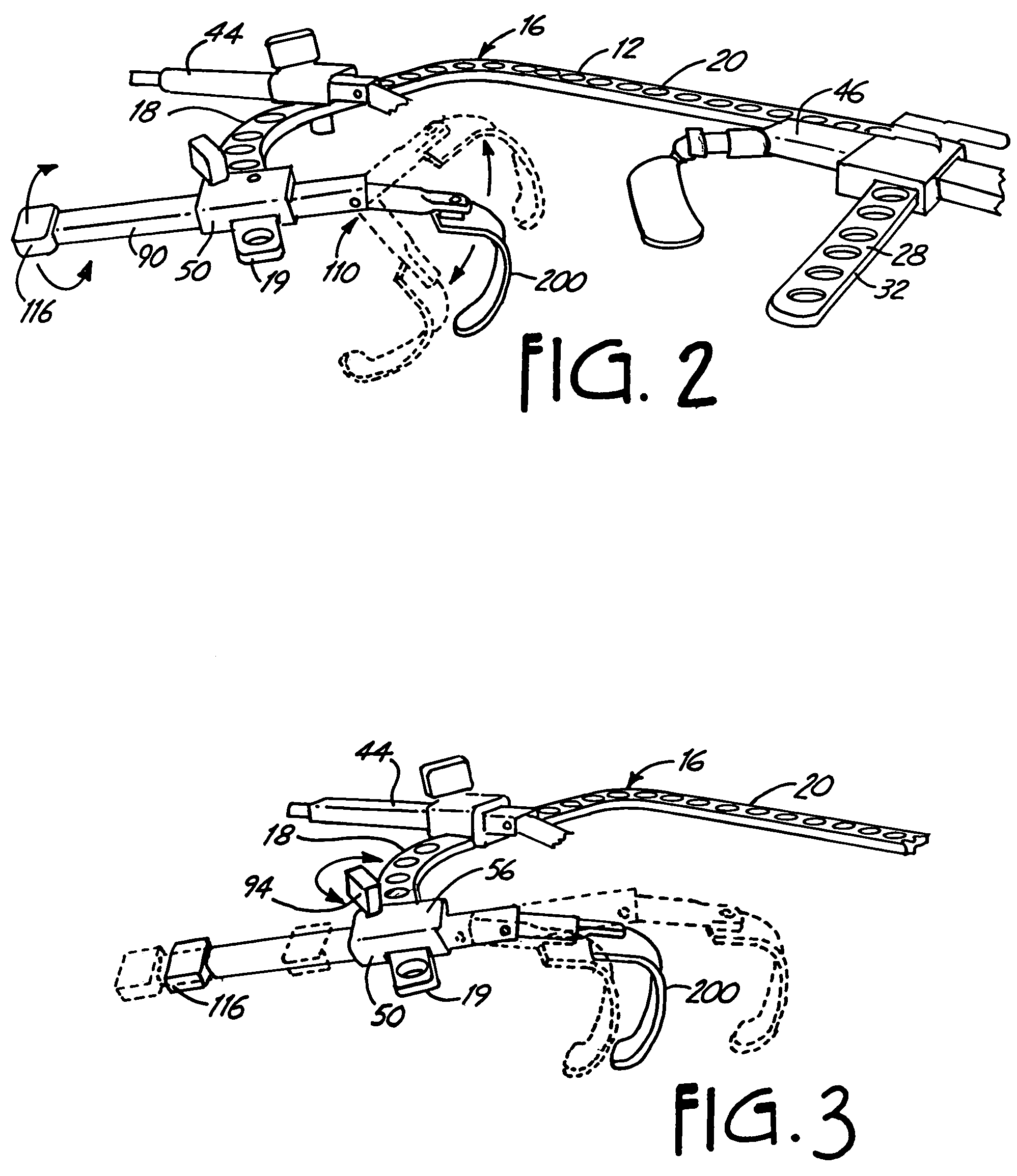
[0021]To provide adequate support around the shoulder while maintaining access to the shoulder to be operated upon, the generally J-shaped member 16 is attached to the support member 14 as illustrated in FIG. 1. The generally J-shaped member 16 includes an arcuate portion 18 proximate a first end 19, a substantially straight middle portion 20 and an outwardly extending portion 22 proximate a second end 21. An engaging portion 24 which engages the support member 14 is positioned substantially perpendicular to the outwardly extending portion 22. The engaging portion 24 is designed to engage the docking member disclo...


PUM


Abstract

A method for performing surgery on a shoulder joint utilizes one positionable support arm attached to a retractor support apparatus. The method includes incising a patient to expose the shoulder joint. After exposing the shoulder joint, the humeral ball is dislocated from the glenoid cavity. A retractor is mounted to one of the support arms at a proximal end. A humerus retractor blade at a distal end of the humerus retractor engages the humerus. The humerus retractor blade is positioned about the humerus and a mechanical system within the humerus retractor is manipulated to laterally displace the humeral ball from the glenoid cavity.

Description

CROSS-REFERENCE TO RELATED APPLICATION(S)[0001]This is a Continuation of application Ser. No. 10 / 077,693, filed Feb. 15, 2002 now U.S. Pat. No. 6,659,944 which is a Continuation of application Ser. No. 09 / 990,420 filed on Nov. 21, 2001 and resulting in U.S. Pat. No. 6,368,271.BACKGROUND OF THE INVENTION[0002]The present invention relates to a method of surgical retraction. In particular, the present invention relates to a method of retracting the humerus during shoulder surgery.[0003]Total shoulder replacement (arthroplasty) operations have been performed for many decades to repair shoulder components. These components include the glenoid cavity (socket portion of the shoulder) and the humeral head (ball portion of the shoulder). The shoulder is typically replaced due to a gradual deterioration or wearing of the glenoid cavity and / or the humeral head or ball. Common causes of the deterioration of the shoulder joint from smooth surfaces where the joint is properly articulating to rou...

Claims


Application Information

Patent Timeline
Patent Type & Authority Patents(United States)
IPC IPC(8): A61B1/32A61B17/02
CPCA61B17/025
Inventor SHARRATT, TODD W.
Owner MINNESOTA SCI
Why Eureka
Try Eureka