Illumination push switch unit

a push switch and push switch technology, applied in the direction of instruments, dashboard fitting arrangements, transportation and packaging, etc., can solve the problems of the operation panel (case) and the switch operation knob b>54/b> not being used

Active Publication Date: 2007-09-04
ALPS ALPINE CO LTD
View PDF6 Cites 55 Cited by
  • Summary
  • Abstract
  • Description
  • Claims
  • Application Information

AI Technical Summary

Problems solved by technology

That is, there is a problem in that the operation panel (case) and the switch operation knob 54 can not be used for the distribution illumination type in which the light-emitting unit is provided on the extending line of the barrier wall.

Method used


Image

  • Illumination push switch unit
  • Illumination push switch unit
  • Illumination push switch unit

Examples


Embodiment Construction

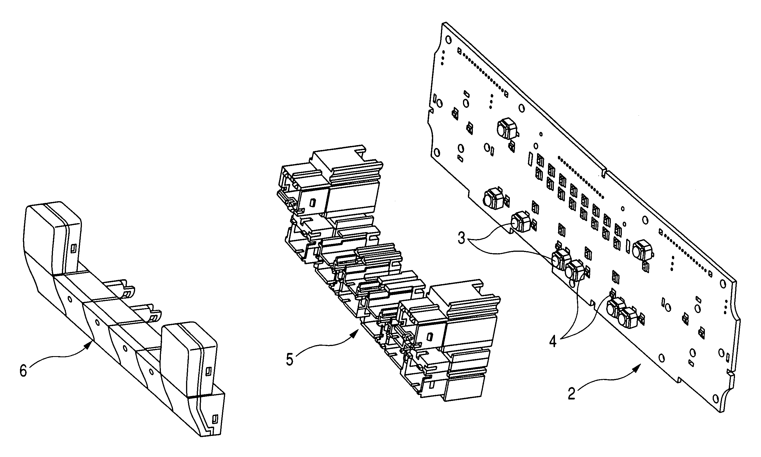
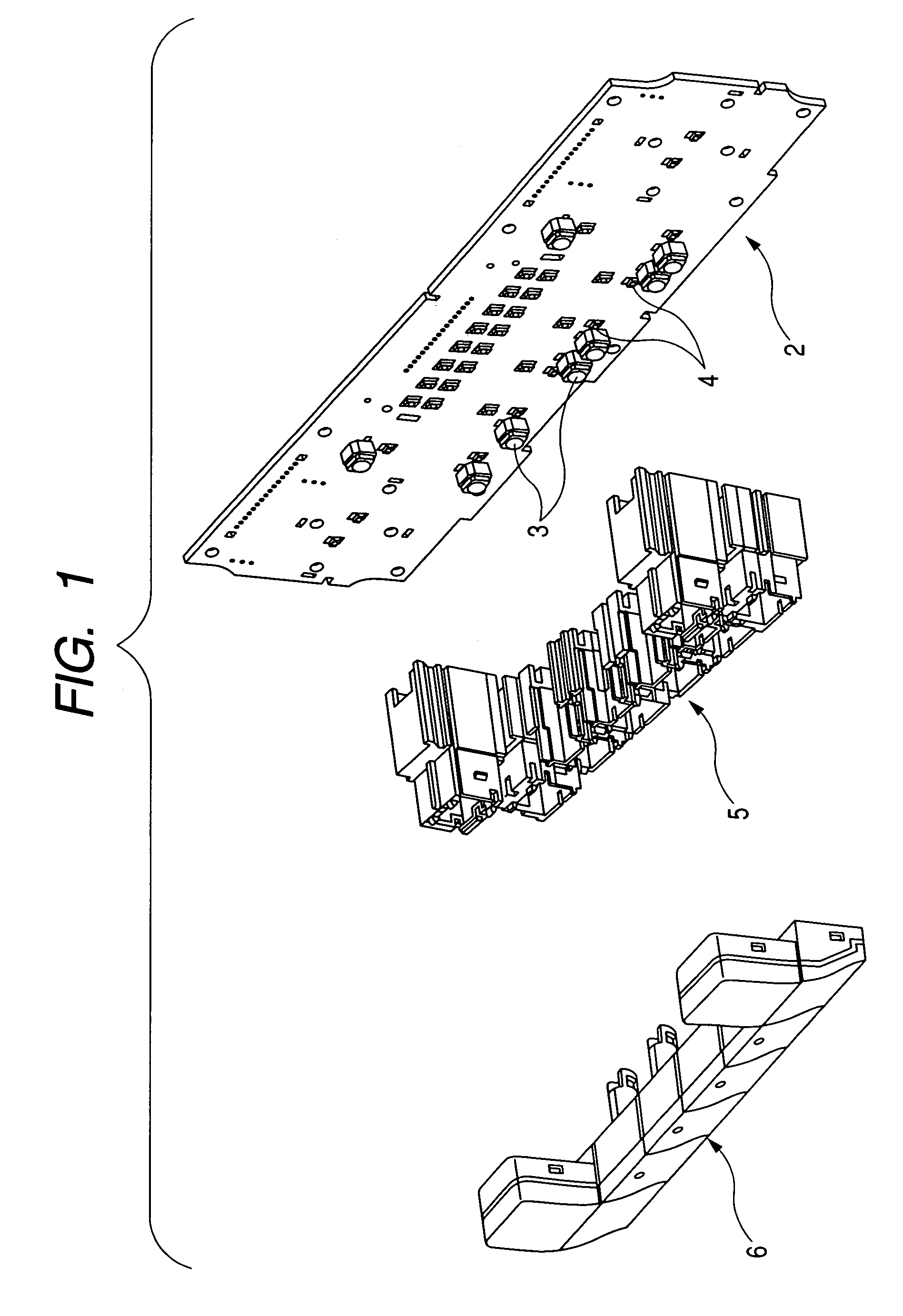
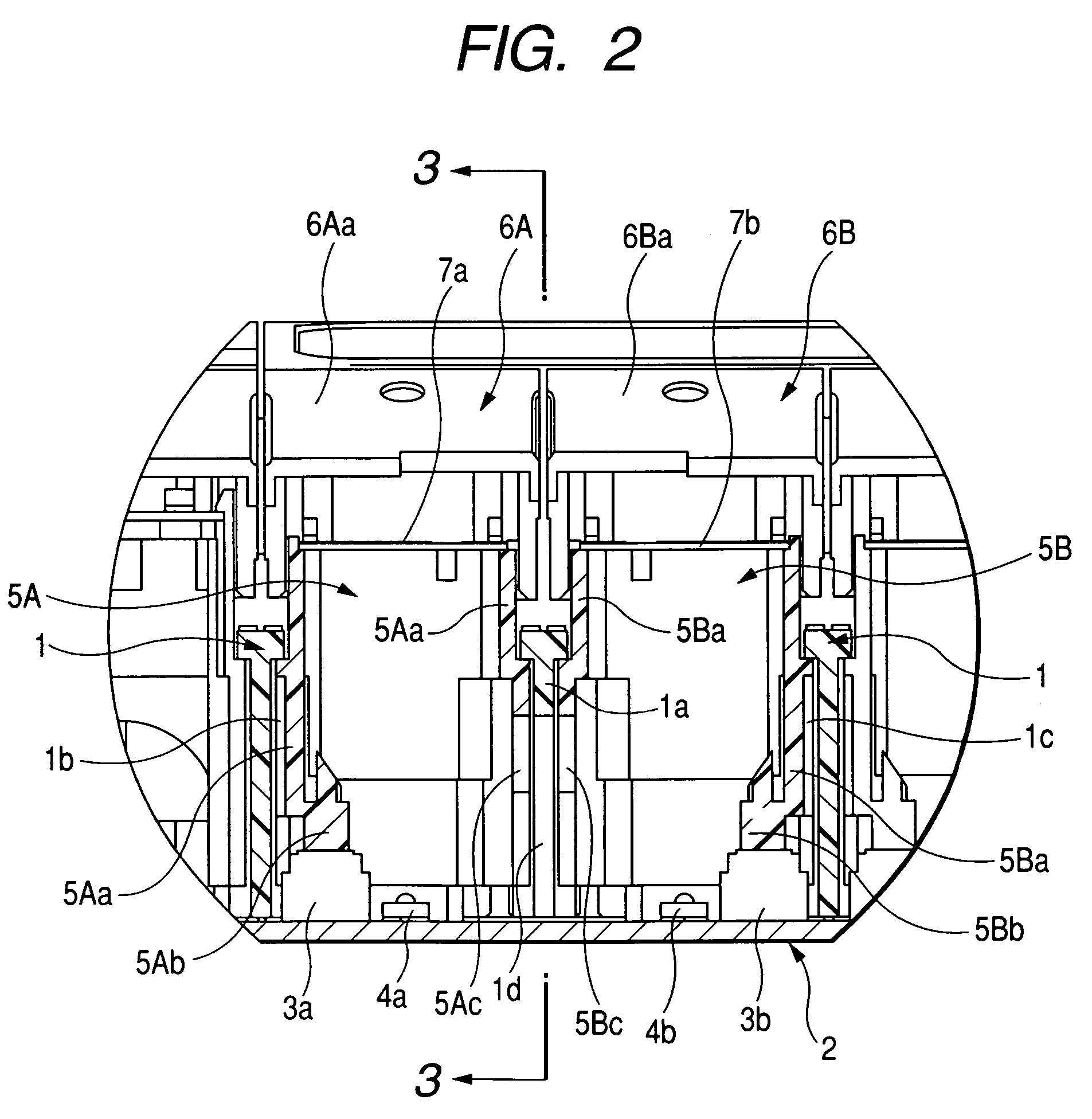
[0024]Hereinafter, an embodiment of the invention is shown in FIGS. 1 to 6. FIG. 1 is a perspective view illustrating an illumination push switch unit according to an embodiment of the invention; FIG. 2 is a cross-sectional view illustrating essential elements of the illumination push switch unit according to the embodiment of the invention; FIG. 3 is a cross-sectional view taken along the line III-III of FIG. 2; FIG. 4 is a perspective view illustrating a structure in which the illumination push switch unit of the invention is applied to a distribution illumination type; FIG. 5 is a cross-sectional view of essential elements shown in FIG. 4; and FIG. 6 is a cross-sectional view taken along the line VI-VI of FIG. 5.

[0025]In FIGS. 1 to 3, an illumination push switch unit of the invention mainly includes a case 1 composed of a housing made of a synthetic resin or the like, an insulating substrate 2 which is fixed to the case 1 and in which a plurality of detecting units 3 and a plural...


PUM


Abstract

An illumination push switch unit is provided in which driving units for driving first and second detecting units are formed at side walls other than adjacent side walls of peripheral walls of first and second sliders with a barrier walls of a case interposed therebetween, notch portions are provided at the bottom surface side of the barrier wall and the bottom surface sides of the adjacent side walls of the peripheral walls with the barrier wall interposed therebetween, and a space portion, which becomes an optical path toward the display surfaces of the first and second operation members, is formed between the top surface of the insulating substrate and the notch portions through the notch portions.

Description

BACKGROUND OF THE INVENTION[0001]1. Field of the Invention[0002]The present invention relates to a structure of an illumination push switch unit which is illuminated from an inner side, as in an electric apparatus.[0003]2. Description of the Related Art[0004]In recent years, various electric apparatuses, such as a television or a navigation system, an audio apparatus like CDs or cassettes, and an air conditioner, have been mounted in a vehicle. Further, various display units, such as characters or figures, are provided on operation surfaces of switch operation knobs for operating switches so as to clearly discriminate the switch operation knobs. Furthermore, in order to improve operability at night, each display unit is constructed such that it is a transmissive type and is illuminated through illumination from an inner side.[0005]There has been known a structure for the illumination of such a switch operation knob (for example, see JP-A-2003-208835). According to the structure, lig...

Claims


Application Information

Patent Timeline
Patent Type & Authority Patents(United States)
IPC IPC(8): H01H9/00
CPCB60K37/06B60Q3/044H01H21/025H01H21/24B60K2350/203B60Q3/14B60K2370/33
Inventor MIYASAKA, YASUHIRONAM, JUNGKIL
Owner ALPS ALPINE CO LTD
Why Eureka
Try Eureka