Micro electric power converter

a converter and micro-chip technology, applied in the direction of electrical apparatus construction details, electrical circuit non-printed electric components association, inductance, etc., can solve the problems of circuit malfunction, circuit malfunction, narrow mounting area of power supply modules, etc., and achieve the effect of magnetic flux density lowering and magnetic

Active Publication Date: 2007-09-11
FUJI ELECTRIC CO LTD
View PDF4 Cites 36 Cited by
  • Summary
  • Abstract
  • Description
  • Claims
  • Application Information

AI Technical Summary

Benefits of technology

[0025]Also advantageously, the voltages of the signals transmitted through the first terminals are the power supply voltage of a control circuit, the ground voltage of the control circuit, and the voltages of the analog signals inputted to and outputted from the control circuit, which can easily cause any circuit malfunction.
[0030]According to the first embodiment of the invention, a circuit malfunction is prevented from arising by arranging the terminals along the Y-direction, where the magnetic flux density may be lowered.
[0031]According to the second embodiment of the invention, a circuit malfunction is prevented from arising by arranging the terminals, through which the signals most adversely affected by the induced voltages are transmitted, along the Y-direction, where the magnetic flux may be lowered, and by arranging the terminals through which the signals least affected by the induced voltage are transmitted, along the X-direction, where the magnetic flux density is high.

Problems solved by technology

However, since these technologies mount discrete component parts on a base board, it is limited to narrowing the mounting area for the power supply module.
Especially, since the magnetic induction component parts such as inductors and transformers are much more bulky than the integrated circuit, the magnetic induction parts represent the greatest challenge for down-sizing the hand held devices.
The large noises further cause a malfunction of the circuit.
Especially when the noises are superimposed on a VDD terminal, a CGND terminal, and an IN terminal, circuit malfunction very often results.
Especially when ferrite substrate 62 is small, or the current made to flow through the coil is high, the magnetic flux density is high, thereby causing circuit malfunctions.

Method used


Image

  • Micro electric power converter
  • Micro electric power converter
  • Micro electric power converter

Examples


first embodiment

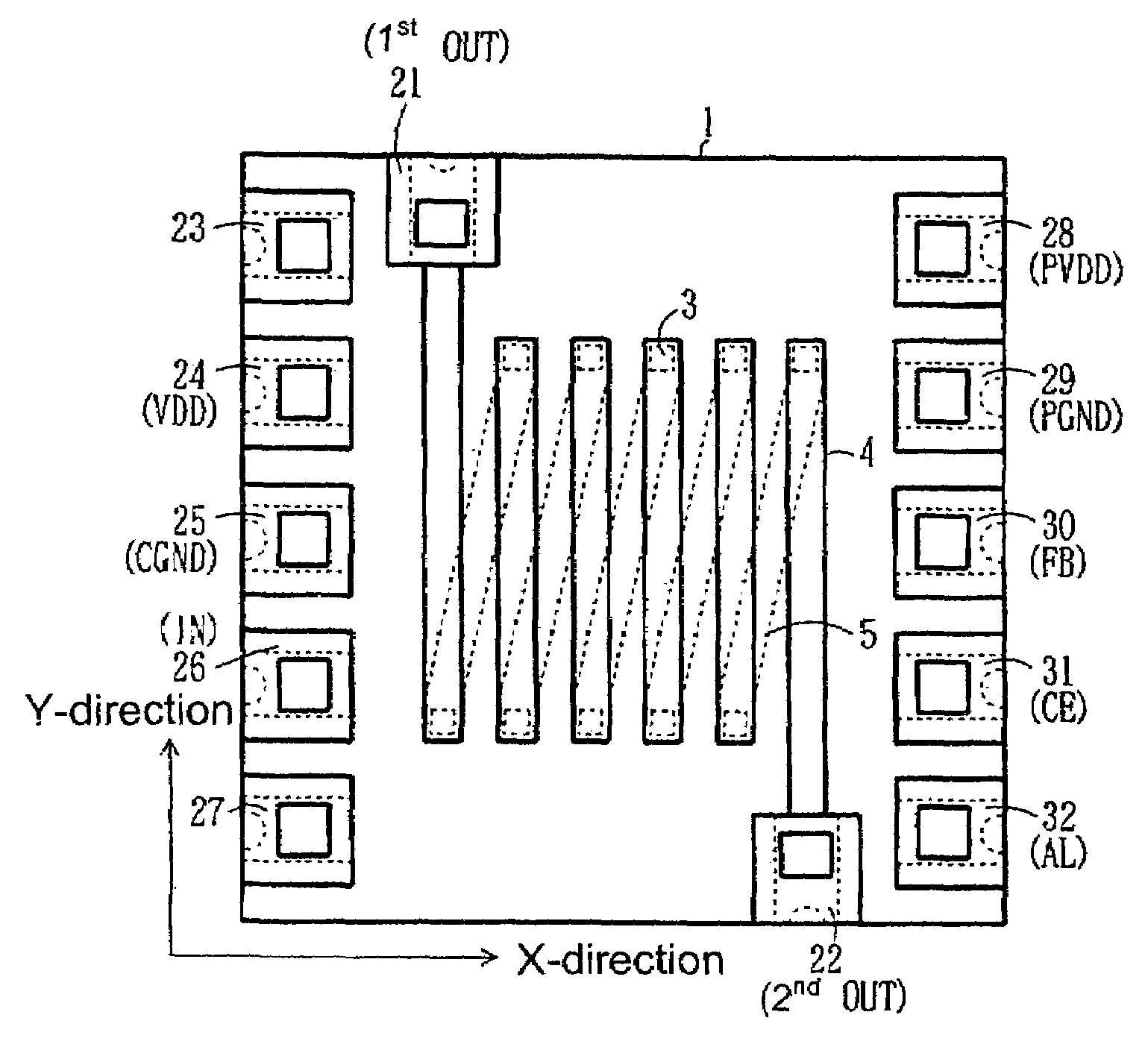
[0040]FIG. 1 is a top plan view of a thin film magnetic induction element constituting a micro electric power converter according to the invention. In FIG. 1, the direction perpendicular to the cross section of a solenoid coil (the axial direction of the coil) is designated to be the X-direction, and the direction perpendicular to the X-direction is designated to be the Y-direction. In FIG. 1, the same reference numbers and symbols as used in FIG. 6 are used to designate the same constituent elements.

[0041]Referring now to FIG. 1, the thin film magnetic induction element according to the first embodiment includes a ferrite substrate 1; a coil formed across ferrite substrate 1 and including connection conductors 3 and coil conductors 4 and 5; and terminals 21 through 32 formed on the perimeter portions of ferrite substrate 1. Terminals 23 through 32 are arranged along the Y-direction, in which the magnetic flux density is low.

[0042]Since a first OUT terminal and a second OUT terminal...

second embodiment

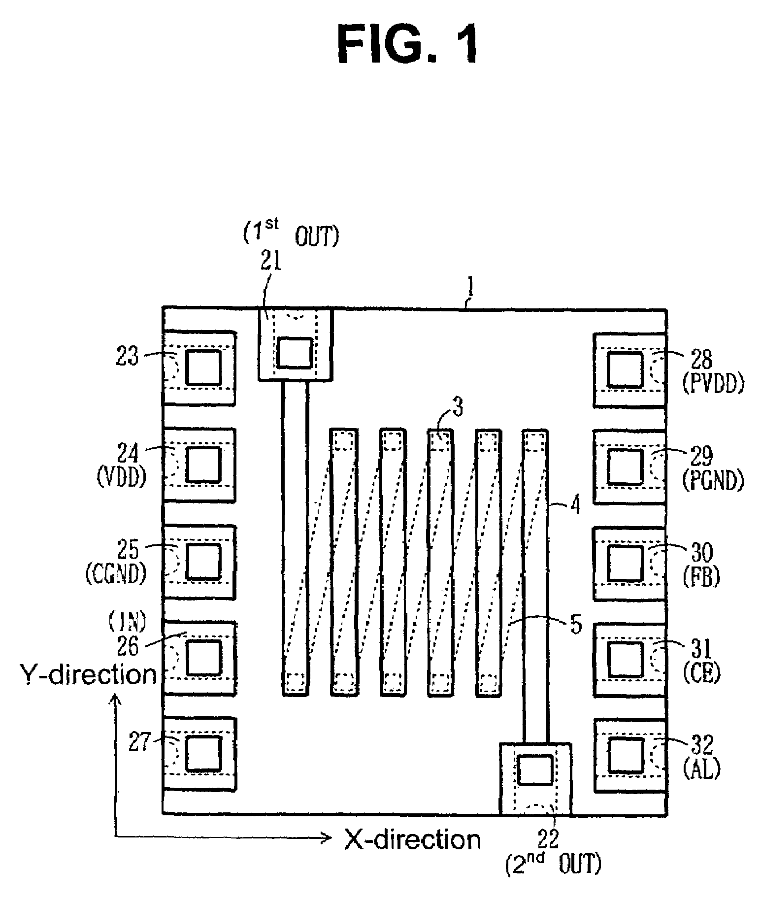
[0046]FIG. 2 is a top plan view of a thin film magnetic induction element constituting a micro electric power converter according to the invention. In FIG. 2, the axial direction of a solenoid coil is designated to be the X-direction, and the direction perpendicular to the X-direction is designated to be the Y-direction. In FIG. 2, the same reference numbers and symbols as used in FIG. 6 are used to designate the same constituent elements.

[0047]Referring now to FIG. 2, the thin film magnetic induction element according to the second embodiment includes a ferrite substrate 2; a coil formed across ferrite substrate 2 and including connection conductors 3 and coil conductors 4 and 5; and terminals 21, 22, 41 through 50 formed on the perimeter portions of ferrite substrate 2. Terminals 41 through 46 are arranged along the Y-direction, in which the magnetic flux density is low. Terminals 21, 22, 47, 48, 49, and 50 are arranged along the X-direction, in which the magnetic flux density is ...

third embodiment

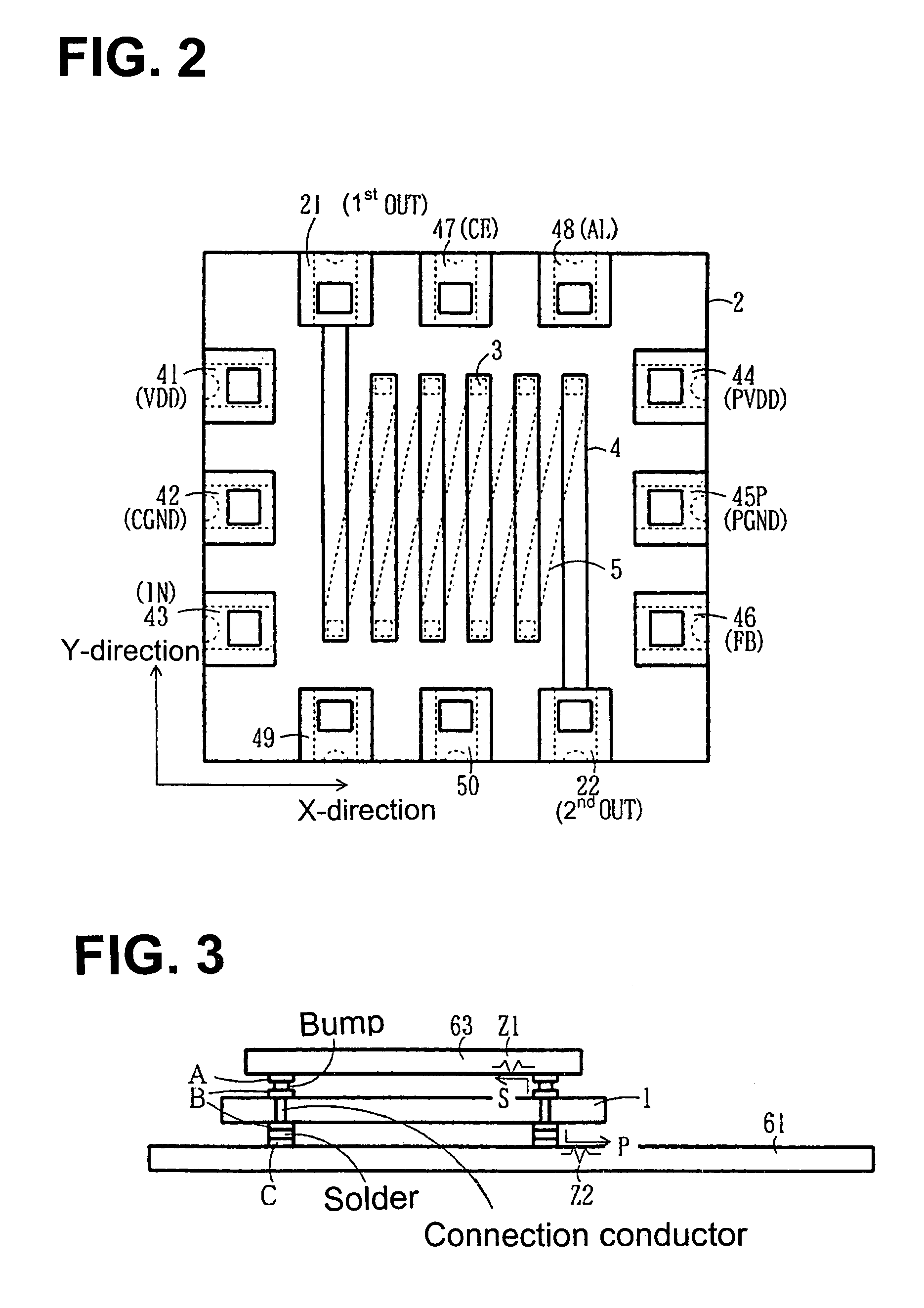
[0055]FIG. 3 is a cross-sectional view of a micro electric power converter according to the invention. Referring now to FIG. 3, terminals B (e.g. terminals 21 through 32 in FIG. 1) formed on the upper surface of thin film magnetic induction element L (including ferrite substrate 1) are fixed to terminals A formed on semiconductor chip 63 shown in FIGS. 4 and 5.

[0056]Terminals B (e.g. terminals 21 through 32 in FIG. 1) formed on the lower surface of thin film magnetic induction element L are connected to terminals C formed on printed circuit board 61. Terminals 21 through 32 shown in FIG. 1 are formed on the front and back surface sides of ferrite substrate 1. The terminals formed on both surface sides of ferrite substrate 1 and designated by the same reference number are connected electrically to each other with a connection conductor extended through ferrite substrate 1.

[0057]Terminals A formed on semiconductor chip 63 are connected to control circuit 64 and such a circuit formed i...


PUM

PropertyMeasurementUnit
thicknessaaaaaaaaaa
currentaaaaaaaaaa
perimeteraaaaaaaaaa

Abstract

A thin film magnetic induction element includes a ferrite substrate, a coil provided across the ferrite substrate and including connection conductors and coil conductors, and terminals provided on perimeter portions of the substrate. Terminals capable of being adversely affected by an induced magnetic flux, such as a VDD terminal, a CGND terminal, an IN terminal, a PVDD terminal, a PGND terminal, an FB terminal, a CE terminal, and an AL terminal are arranged along the Y-direction of the substrate, in which the magnetic flux density is low. Terminals substantially incapable of being adversely affected by an induced magnetic flux are arranged along the X-direction of the substrate, in which the magnetic flux density is high. A micro electric power converter having the thin film magnetic induction element is less susceptible to circuit malfunctions.

Description

BACKGROUND OF THE INVENTION AND RELATED ART STATEMENT[0001]The present invention relates to a micro DC-DC converter and to such a micro electric power converter formed of a semiconductor integrated circuit (hereinafter referred to as an “IC”) and passive component parts such as a coil, a capacitor, and a resistor.[0002]Recently, the popularity of hand held devices has become widespread. Many of the hand held devices use a cell for the electric power source thereof, and incorporate a DC-DC converter and such an electric power converter therein. Usually, the electric power converter, including active devices such as switching devices and a control IC, and passive individual component parts such as a coil, a transformer, a rectifier, a capacitor, and a resistor, is configured as a hybrid module, and is mounted on a printed circuit board such as a ceramic board and a plastic board.[0003]FIG. 4 is a block circuit diagram of a conventional DC-DC converter. In FIG. 4, the conventional DC-D...

Claims


Application Information

Patent Timeline
Patent Type & Authority Patents(United States)
IPC IPC(8): H01F5/00
CPCH01F17/0033H01F27/292H01L23/15H01L23/49822H01L23/49838H01L23/66H02M3/155H01L2224/16235H01L2924/13091H01L2924/15311H01L2924/19015H01L2924/3011H01L2224/16H01L2224/05573H01L2224/05568H01L2924/00014H01L2224/0554H01L2224/05599H01L2224/0555H01L2224/0556
Inventor NISHIO, HARUHIKOKATAYAMA, YASUSHI
Owner FUJI ELECTRIC CO LTD
Why Eureka
Try Eureka