
Tooth and friction lightering arrangement

a lightering arrangement and friction technology, applied in the direction of tugs, vessel construction, towing/pushing equipment, etc., can solve the problems of substantial damage and injury, the loading barge is pushed, and the longitudinal control is lost, so as to minimize the amount of time, minimize the potential for a loss of longitudinal control, and minimize the effect of undesirable movemen

Active Publication Date: 2007-09-18
INTERCONTINENTAL ENG MFG
View PDF3 Cites 2 Cited by
  • Summary
  • Abstract
  • Description
  • Claims
  • Application Information

AI Technical Summary

Benefits of technology

[0009]The present invention provides a system that allows for coupling a first vessel, such as a tugboat or other pusher vessel, with a second vessel, such as an unpowered barge, to minimize undesirable movement therebetween while allowing for lightering, i.e., compensating for changes in the relative vertical positions, or draft differential, of the vessels as weight is added to or removed from one or both of the vessels. More specifically, the system minimizes the amount of time required to reengage the vessels during lightering, and thereby minimizes the potential for a loss of longitudinal control and for the first vessel to roll in the notch.

Problems solved by technology

For example, when a barge is used to transport oil, the coupling of the tugboat to the barge, the loading of the barge, and the actual pushing of the loaded barge take place on open sea and are subject to substantial waves.
The tugboats must be securely connected to the barges to prevent the tugboats from being tossed against the barges, otherwise substantial damage and injury can occur.
As the barge is loaded, the weight of the load will cause the barge to sit lower in the water.
If the tugboat were to remain fixedly connected to the barge during the loading operation, the weight of the load would push the tugboat down into the water, with possibly disastrous consequences.
With this type of connection, any contact between the coupler heads and the barge when disengaged can causes the rams to rotate, thereby misaligning the respective teeth and making reengagement difficult.
Furthermore, complete disengagement results in a loss of longitudinal and tugboat roll control.
Any time that the rams disengage from the receivers, there is a potential for mishap, especially in rough wave or wind action.

Method used


Image

  • Tooth and friction lightering arrangement
  • Tooth and friction lightering arrangement
  • Tooth and friction lightering arrangement

Examples


Embodiment Construction

, below.

BRIEF DESCRIPTION OF THE DRAWING FIGURES

[0013]A preferred embodiment of the present invention is described in detail below with reference to the attached drawing figures, wherein:

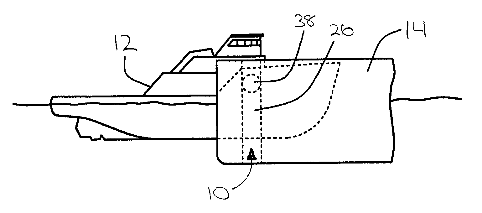
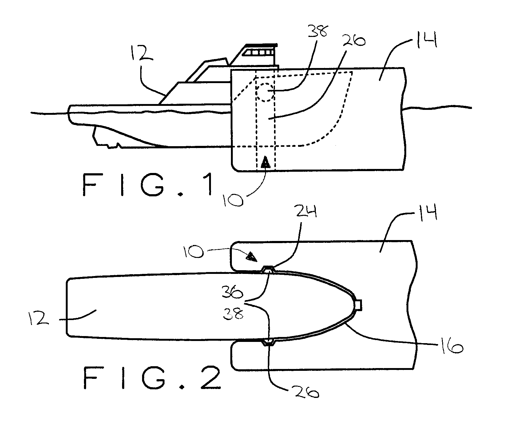
[0014]FIG. 1 is an elevation view of a first vessel received within a notch of a second vessel;

[0015]FIG. 2 is a plan view of the first vessel received within the notch of the second vessel;

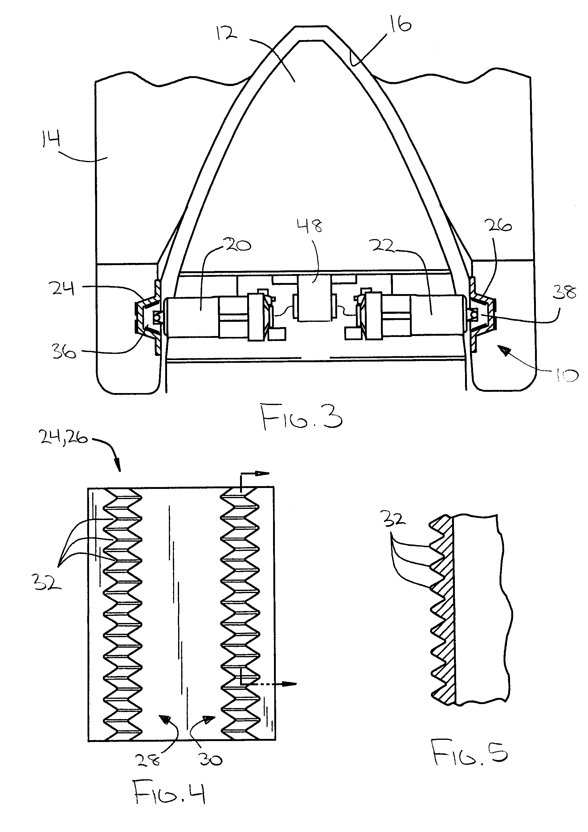
[0016]FIG. 3 is a fragmentary sectional plan view of an embodiment of the vessel coupling system of the present invention;

[0017]FIG. 4 is a fragmentary elevation view of a receiver portion of the vessel coupling system;

[0018]FIG. 5 is a fragmentary sectional view of the receiver portion of FIG. 4;

[0019]FIG. 6 is an elevational view of a coupling head portion of the vessel coupling system;

[0020]FIG. 7 is a fragmentary sectional plan view of the receiver and coupling head in a first configuration;

[0021]FIG. 8 is a fragmentary section elevation view of the receiver and coupling head in the first configuration;

[0022]...


PUM


Abstract

A system (10) for coupling first and second vessels (12,14) to minimize movement therebetween while allowing for lightering. The system (10) comprises rams (20,22) and coupling heads (36,38) associated with the first vessel (12), and receivers (24,26) associated with the second vessel (14) for receiving the coupling heads (36,38). The system (1) allows for at least three configurations: a first configuration in which the rams (20,22) are extended and the coupling heads (36,38) are rotated such that first faces (42) interlock with the receivers (24,26); a second configuration in which the rams (20,22) are extended and the coupling heads (36,38) are rotated such that second faces (44) abut the receivers (24,26); and a third configuration in which the rams (20,22) are retracted such that the coupling heads (36,38) do not interact with the receivers (24,26). Lightering is accomplished by a series of short-duration switches between the second and third configurations.

Description

CROSS REFERENCE TO RELATED APPLICATIONS[0001]The present non-provisional patent application claims priority benefit of an earlier-filed provisional patent application of the same title, Ser. No. 60 / 762,408, filed Jan. 26, 2006. The identified earlier-filed application is hereby incorporated by reference into the present application.BACKGROUND OF THE INVENTION[0002]1. Field of the Invention[0003]The present invention relates to system and methods for coupling powered pusher vessels to unpowered vessels. More specifically, the present invention concerns a system for coupling a first vessel, such as a tugboat or other pusher vessel, with a second vessel, such as an unpowered barge, to minimize undesirable movement therebetween while allowing for lightering, i.e., compensating for changes in the relative vertical positions, or draft differential, of the vessels as weight is added or removed from one or both of the vessels.[0004]2. Background of the Invention[0005]Barges are used to tran...

Claims


Application Information

Patent Timeline
Patent Type & Authority Patents(United States)
IPC IPC(8): B63B21/56
CPCB63B21/56B63B35/70
Inventor KUHLMAN, CLARE J.
Owner INTERCONTINENTAL ENG MFG
Learn More