Stator designed to minimize leakage current and electric rotating machine using same

a technology of electric rotating machines and static generators, applied in the field of static generators, can solve problems such as the decrease of leakage current, and achieve the effect of minimizing undesirable movemen

Active Publication Date: 2011-07-07
DENSO CORP
View PDF11 Cites 10 Cited by
  • Summary
  • Abstract
  • Description
  • Claims
  • Application Information

AI Technical Summary

Benefits of technology

[0028]The inner insulator may have side walls extending in the radial direction of the stator core. The outer insulator may have side walls extending in the radial direction of the stator core. Ends of the side walls of the inner insulator are laid to overlap with ends of the side walls of the outer insulator in the circumferential direction of the stator core. This minimizes an air gap between a radially-outward portion of the array of the in-slot portions and the inner wall of the slot to minimize undesirable movement of the stator winding in the circumferential direction of the stator core.
[0029]The ends of the side walls of the inner insulator are folded back. The ends of the side walls of the inner insulator may be folded inwardly of the inner insulator. This insulates a radially-outward portion of the array of the in-slot portions in the form of three layers, thereby filling the air gap to hold the stator winding from moving in the circumferential direction of the stator core.

Problems solved by technology

This results in a great decrease in leakage current.

Method used


Image

  • Stator designed to minimize leakage current and electric rotating machine using same
  • Stator designed to minimize leakage current and electric rotating machine using same
  • Stator designed to minimize leakage current and electric rotating machine using same

Examples


first embodiment

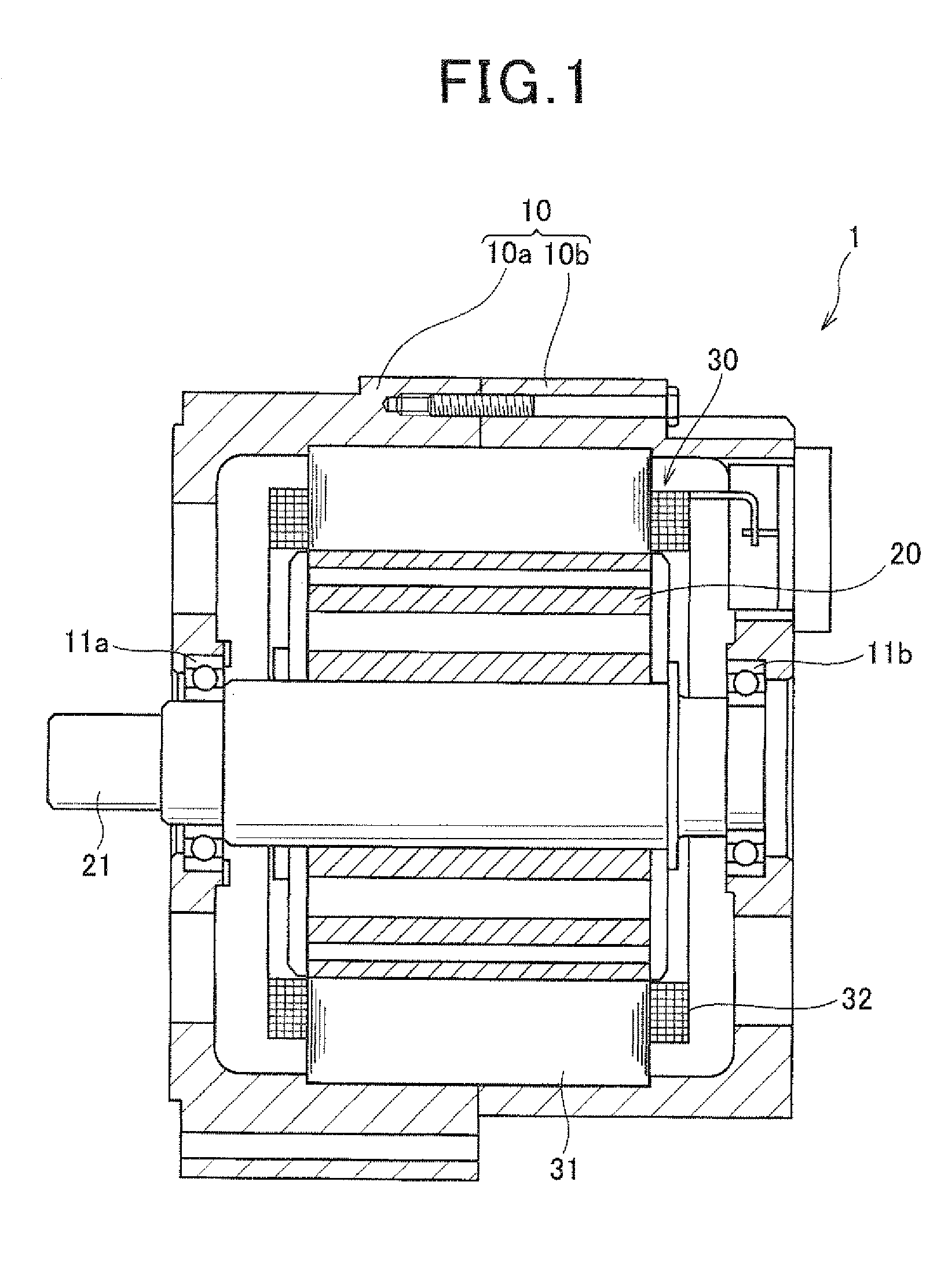
[0054]Referring to the drawings, wherein like reference numbers refer to like parts in several views, particularly to FIG. 1, there is shown an electric rotating machine 1 according to the invention which is designed to be installed in automotive vehicles as an electric motor, an electric generator, or a generator-motor.

[0055]The electric rotating machine 1 is equipped with a hollow cylindrical housing 10, a rotor 20, and a stator 30. The housing 10 is made up of a front cup 10a and a rear cup 10b which are joined at openings thereof together. The front and rear cups 10a and 10b have installed therein bearings 11a and 11b through which a rotating shaft 21 is retained to be rotatable.

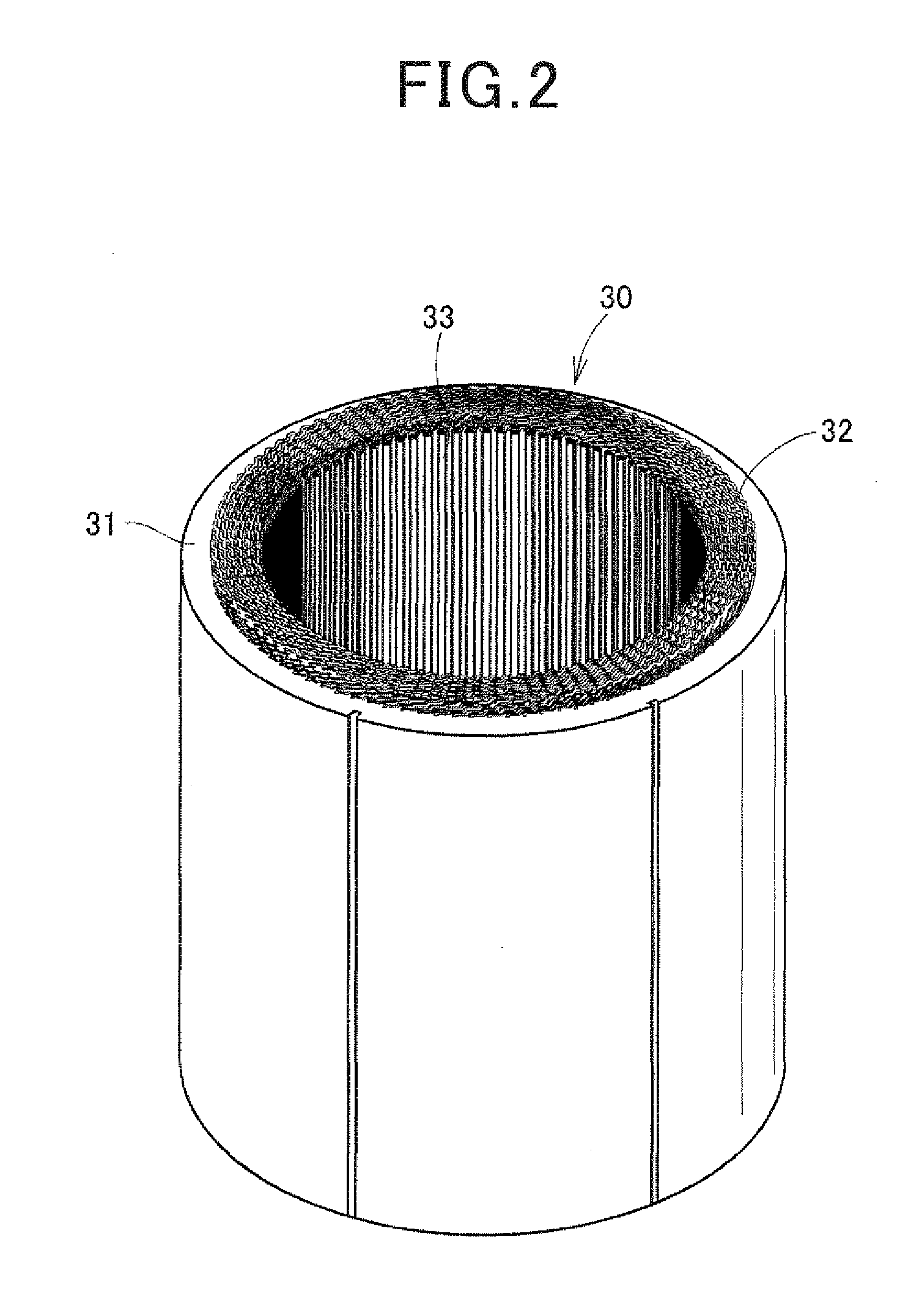
[0056]The rotor 20 is fit on the rotating shaft 21 to be rotatable together. The stator 30 is disposed inside the housing 10 and surrounds the periphery of the rotor 20. The rotor 20 has a plurality of permanent magnets arrayed on an outer circumference thereof facing an inner circumference of the stator...

second embodiment

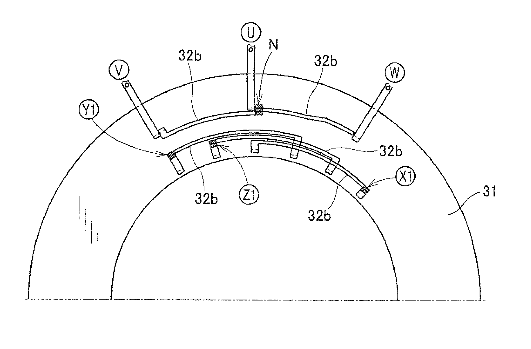
[0095]As apparent from the above explanation, the second winding 38 of the U-phase winding 32u is disposed in the first layer position (i.e., the outermost position) within No. 3, No. 9, and No. 12 slots 33. The first winding 37 and the second winding 38 are placed alternately with in the slot 33 in the radially inward direction of the stator core 31. No. 6 slot 33 makes an exception and is different in layout of the in-slot portions 32a of the stator winding 32 from the other slots 33 because the end U of the U-phase winding 32u needs to extend outside the stator core 31. Similarly, the second winding 38 of the V-phase winding 32v is disposed in the first layer position within each of three of the four slits 33. The first winding 37 and the second winding 38 are placed alternately with in each of the three slot 33 in the radially inward direction of the stator core 31. The remaining one slot 33 is different in layout of the in-slot portions 32a of the stator winding 32 from the oth...


PUM


Abstract

A stator which may be employed in an electric rotating machine. The stator includes a stator winding which includes in-slot portions disposed in slots of a stator core. The in-slot portions are arrayed in each of the slots in a form of multiple layers aligned in a radial direction of the stator core. The stator winding is made up of a first winding and a second winding which are connected together through a joint. The first winding is defined by a portion of the stator winding between the joint and an end of the stator winding which is to be connected to an external. The second winding includes the in-slot portion placed within at least one of the slots as an outermost layer that is one of the layers placed most outwardly in the radial direction of the stator core. This results in a great decrease in leakage current.

Description

CROSS REFERENCE TO RELATED DOCUMENT[0001]The present application claims the benefit of priority of Japanese Patent Application No. 2010-1960 filed on Jan. 7, 2010, the disclosure of which is incorporated herein by reference.BACKGROUND OF THE INVENTION[0002]1. Technical Field of the Invention[0003]The present invention relates generally to a stator which may be used with an electric rotating machine and designed to minimize leakage current, and an electric rotating machine equipped with such a stator.[0004]2. Background Art[0005]Japanese Patent First Publication No. 2009-112186, assigned to the same assignee as that of this application, discloses an electric rotating machine equipped with a hollow cylindrical stator in which a plurality of slots are formed. The slots extend in an axial direction of the stator. The stator is equipped with a stator winding made of wire. The stator winding has in-slot portions and turned portions. The in-slot portions are disposed inside the slots. Each...

Claims


Application Information

Patent Timeline
Patent Type & Authority Applications(United States)
IPC IPC(8): H02K3/28
CPCH02K3/12H02K3/345H02K3/28
Inventor FUKUSHIMA, AKIRAKONDO, KEIJIAKIMOTO, AKITOMAEKAWA, TAKEOTANIGUCHI, MAKOTOKUSASE, SHIN
Owner DENSO CORP
Why Eureka
Try Eureka