Automatic pet food dispensing device

a pet food and automatic technology, applied in animal feeding devices, aviculture, animal husbandry, etc., can solve the problems of affecting the smooth flow of pet food dispensing devices, jamming, and serious problems of pet food dispensers of prior arts, and achieve the effect of not ensuring the smooth flow intended by the designer of the pet food dispensing devi

Inactive Publication Date: 2007-09-18
PARK SUNG HO
View PDF18 Cites 17 Cited by
  • Summary
  • Abstract
  • Description
  • Claims
  • Application Information

AI Technical Summary

Benefits of technology

[0007]Accordingly, it is an object of the present invention to provide an automatic pet food dispensing device that prevents the jamming of the feeder by the food.

Problems solved by technology

Pet food dispensers of prior arts have a serious problem, jamming, among many others.
Since it was supposed to be automatic, the jammed pet food dispensing device is outright trouble to the pets and to the pet owners who are trusting the device and traveling for a couple of days.
The fact that the grains of pet food is small compared to the opening through which the pet food is led does not guarantee a smooth flow intended by the designer of the pet food dispensing device.

Method used


Image

  • Automatic pet food dispensing device
  • Automatic pet food dispensing device
  • Automatic pet food dispensing device

Examples


first embodiment

[0072]FIGS. 1 through 20 show the invention.

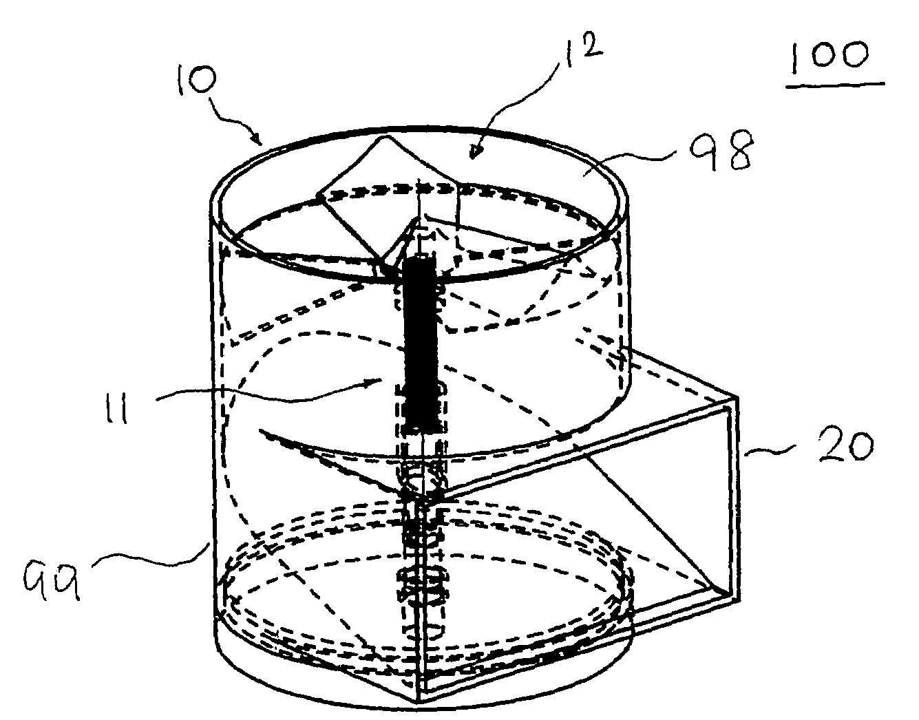
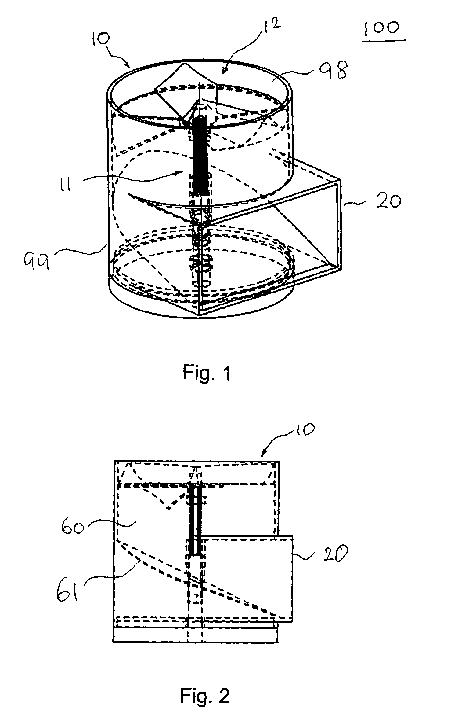
[0073]In the first embodiment of the invention, an automatic pet food dispensing device 100 includes a pet food dispenser 10 and an outer case 99 housing the parts.

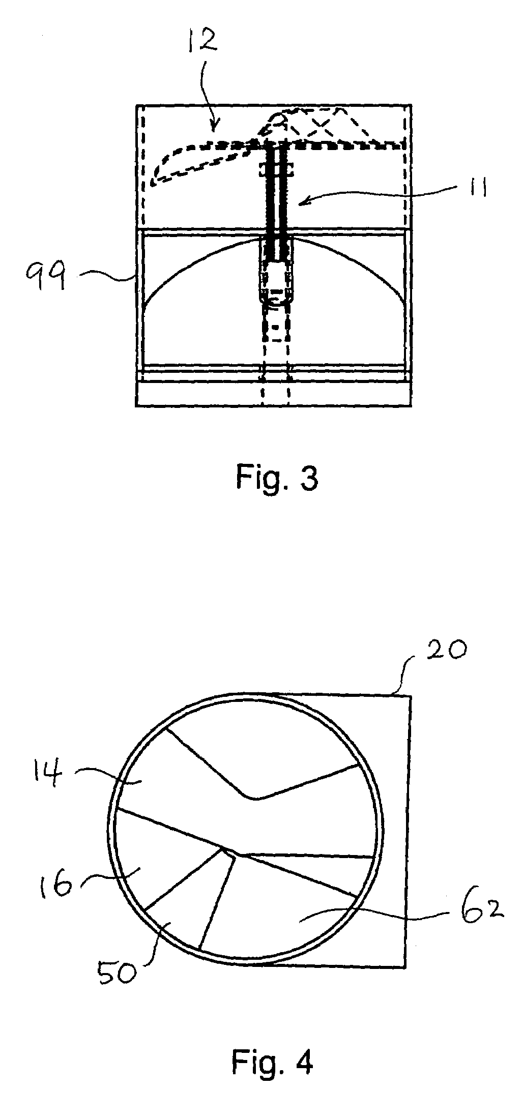
[0074]The pet food dispenser 10 includes a shaft 11, a dispensing disc 12, and a stirrer 30 (refer to FIG. 8) for stirring jammed pet food particles. The dispensing spouts 20 leads the pet food from the space 60 formed by the bottom of dispensing disc 12.

[0075]As shown in FIGS. 1 through 4, the dispensing disc 12 includes a top layer 14 and a bottom layer 16. And the top and bottom layers 14, 16 of the dispensing disc 12 are positioned adjacently. The top layer 14 comprises a top cutout portion 56 and the bottom layer 16 comprises a bottom cutout portion 57. The area of opening or arc recess 62 formed by the top and bottom cutout portions 56, 57 adjustable. The top layer 14 of the dispensing disc 12 includes one or more bumps 18 on the top surface.

[0076]As shown in FIGS. 5 throu...

second embodiment

[0083]FIGS. 21 through 41 show the invention.

[0084]In the second embodiment of the invention, the stirrer 30′ of the pet food dispenser 10′ includes a string member 32. As shown in FIGS. 36 and 40, the dispensing device 200 includes an inner case 70. The string member 32 straddles on grooves 71 provided on the upper perimeter 72 of the inner case 70 of the pet food dispenser 10′. The stirrer 30′ is made of material with high elasticity.

[0085]As shown in FIGS. 25 through 29, the shaft 11′ of the pet food dispenser 10′ includes a head portion 15′, a cylinder portion 13′, partially flattened tail portion 17′, and is fixed securely to the top layer 14′ of the dispensing disc 12′ and engaged with the bottom layer 16′ of the dispensing disc 12′ with a predetermined friction.

[0086]The top layer 14′ has substantially semi-circular shape and the bottom layer 16′ includes a cutout portion 62′, and each of the layers 14′, 16′ includes a first edge 51′, 53′ and a second edge 52′, 54′. The angle...


PUM


Abstract

An pet food dispensing device includes a dispenser, an outer case, a pet food container, a slant guide, a driving device, and dispensing spouts. The dispenser includes a shaft, a dispensing disc, and a stirrer. The dispensing disc includes a top and bottom layers, which are positioned adjacently. The top layer of the dispensing disc includes one or more bumps on the top surface. The stirrer of the pet food dispenser includes a first flap extended from the first edge of the bottom layer of the dispensing disc, and the first flap is bent downwardly below the horizontal plane. In another embodiment, the stirrer includes an inner case and an elastic string member adjacently below the dispensing disc. The angle of the arc recess defined by the top and bottom layers varies from zero to one hundred eighty degrees. An outer case houses all parts.

Description

BACKGROUND OF THE INVENTION[0001]The present invention relates to an improved automatic pet food dispensing device. More particularly, this invention relates to an automatic pet food dispensing device that will prevent the device from jamming in dispensing the pet food.[0002]The related U.S. patent application Ser. No. 10 / 620,662 by the inventor of this invention is incorporated by reference into this disclosure as if fully set forth herein.[0003]Pet food dispensers of prior arts have a serious problem, jamming, among many others. Since it was supposed to be automatic, the jammed pet food dispensing device is outright trouble to the pets and to the pet owners who are trusting the device and traveling for a couple of days.[0004]The fact that the grains of pet food is small compared to the opening through which the pet food is led does not guarantee a smooth flow intended by the designer of the pet food dispensing device. The interaction between pet food particles and the inner wall o...

Claims


Application Information

Patent Timeline
Patent Type & Authority Patents(United States)
IPC IPC(8): A01K1/00
CPCA01K5/0114A01K5/0291A01K5/00A01K5/02
Inventor PARK, SUNG HO
Owner PARK SUNG HO
Why Eureka
Try Eureka