
Method and apparatus for timing adjustment

a timing adjustment and data technology, applied in the direction of information storage, static storage, digital storage, etc., can solve the problems of data mislatch, conventional apparatus may fail to perform a latch timing adjustment with a high precision, and data mislatch may occur

Active Publication Date: 2007-09-18
SOCIONEXT INC
View PDF6 Cites 27 Cited by
  • Summary
  • Abstract
  • Description
  • Claims
  • Application Information

AI Technical Summary

Benefits of technology

Enables precise latch timing adjustment, ensuring data is accurately latched with the strobe signal and subsequently with the system clock, thereby preventing mislatches and improving data transfer reliability.

Problems solved by technology

If the readout data is latched with predetermined fixed latch timing, a data mislatch may occur.
Although the conventional latch timing adjustment apparatus adjusts the phase of the strobe signal so that readout data can be desirably latched with the strobe signal, a mislatch may occur when data, which has been latched with the strobe signal, is latched again with the system clock if there is a displacement in the phase relationship between the strobe signal and the system clock.
Thus, the conventional apparatus may fail to perform a latch timing adjustment with a high precision.

Method used


Image

  • Method and apparatus for timing adjustment
  • Method and apparatus for timing adjustment
  • Method and apparatus for timing adjustment

Examples


first embodiment

Second Variation of First Embodiment

[0093]A second variation of the first embodiment will now be described with reference to FIG. 8.

[0094]This variation is directed to a case where a strobe signal s100a″ from the memory 100 has m bits (m is an integer greater than or equal to 2), and readout data s100b″ from the memory 100 has n bits (n is an integer greater than or equal to 2).

[0095]In FIG. 8, the memory 100 outputs the m-bit strobe signal s100a″ and the n-bit readout data s100b″. For example, the strobe signal s100a″ may have 4 bits, and the readout data s100b″ may have 32 bits, wherein 1 bit of the strobe signal corresponds to 8 bits of the readout data. Accordingly, the apparatus includes a number m of strobe delay selection sections 303 for producing a delayed strobe signal for each of the m bits. Similarly, the apparatus includes a number n of data delay selection sections 304 for producing delayed data for each of the n bits.

[0096]The apparatus includes a number n of strobe l...

second embodiment

First Variation of Second Embodiment

[0119]A first variation of the second embodiment will now be described with reference to FIG. 12.

[0120]In this variation, a change is made to the configuration of the clock delay selection section 403 shown in FIG. 10.

[0121]Specifically, referring to FIG. 12, the clock delay selection section 403 of this variation includes a fixed delay section 4030 and a variable delay section 4031.

[0122]The fixed delay section 4030 receives the system clock s200, and simultaneously produces a plurality of system clocks of different phases from the system clock s200 to selectively output one of the system clocks. Different phases of the system clock s200 can be easily produced by using a PLL circuit or a DLL circuit, for example.

[0123]The variable delay section 4031 includes a series of delay circuits 40311, 40312 to 4031n and a selection section 4031a. The variable delay section 4031 delays a system clock of a phase selected by the fixed delay section 4030 succe...


PUM


Abstract

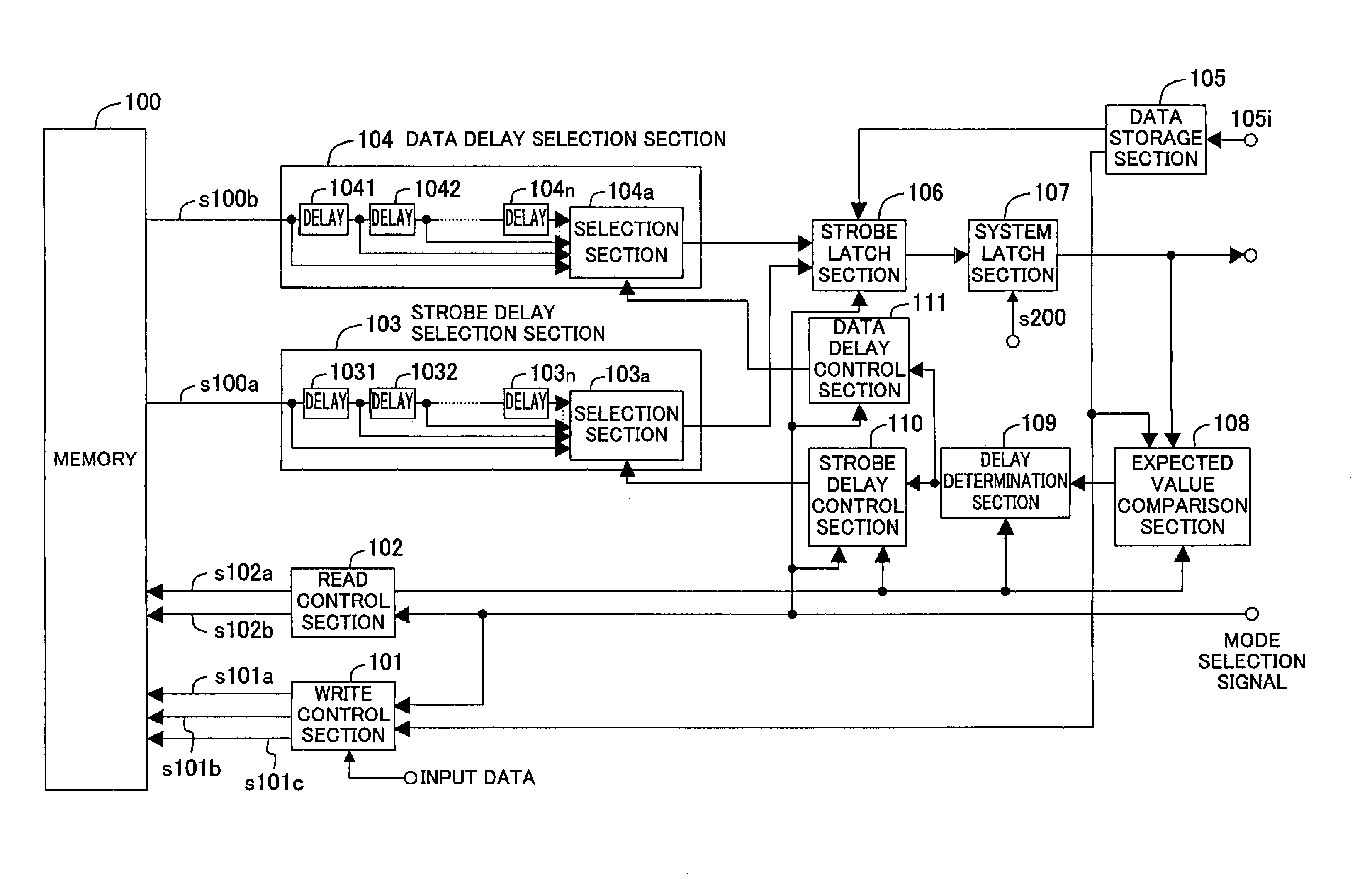
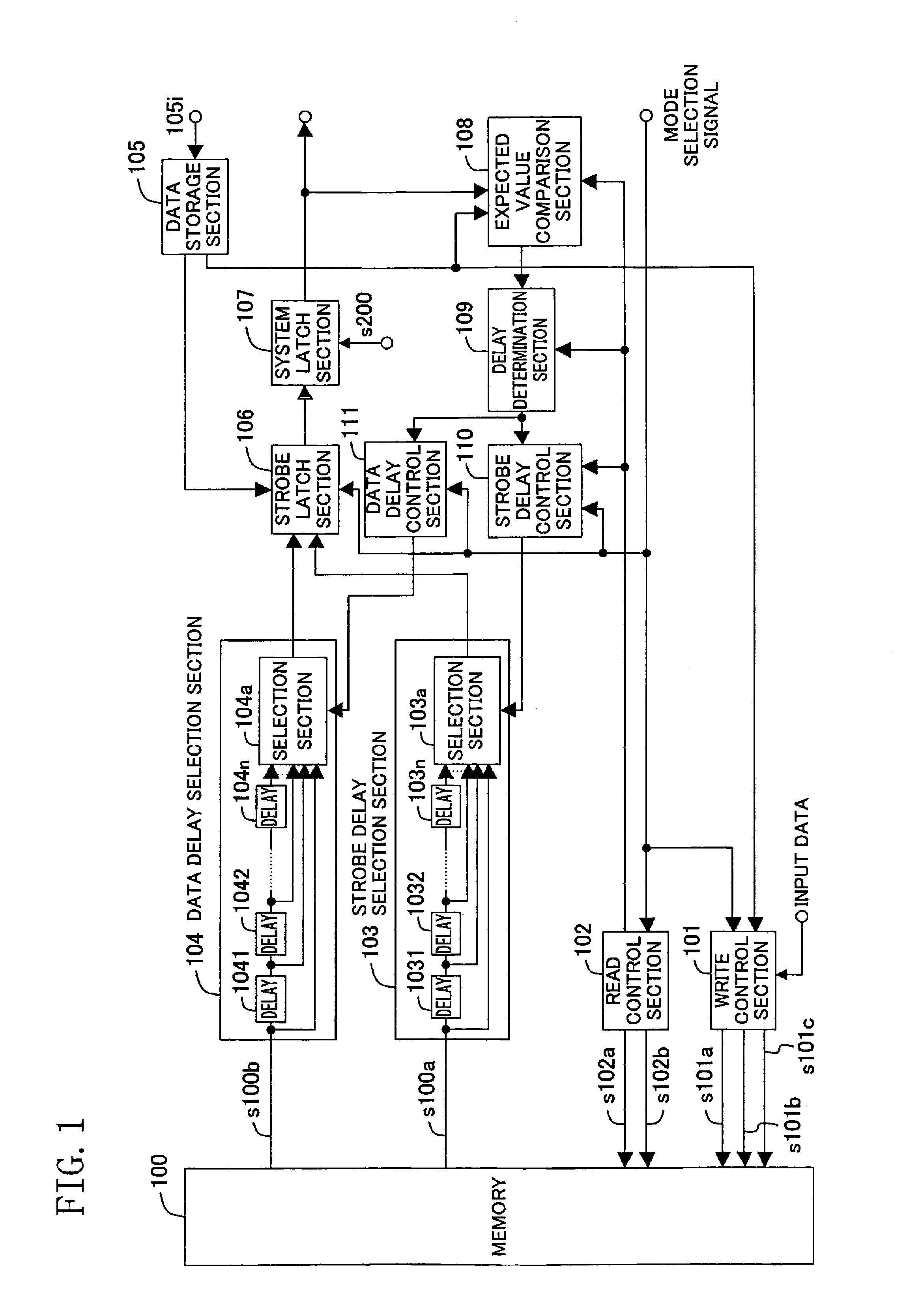
A strobe signal from a memory is delayed through delay circuits of a strobe delay selection section, thus obtaining a plurality of delayed strobe signals. A strobe latch section produces check data in synchronism with each of the delayed strobe signals, and a system latch section latches, with a system clock, check data latched by the strobe latch section. Based on a comparison by an expected value comparison section and a determination by a delay determination section, the optimal strobe signal with the optimal delay is selected from among the delayed strobe signals produced in the strobe delay selection section. Then, data from the memory is delayed through delay circuits in a data delay selection section, thus obtaining a plurality of delayed data, and the optimal data with the optimal delay is selected from among the plurality of delayed data based on the comparison by the expected value comparison section and the determination by the delay determination section.

Description

CROSS REFERENCE TO RELATED APPLICATIONS[0001]This Non-provisional application claims priority under 35 U.S.C. §119(a) on Patent Application No. 2004-381496 filed in Japan on Dec. 28, 2004, the entire contents of which are hereby incorporated by reference.BACKGROUND OF THE INVENTION[0002]The present invention relates to a data timing adjustment method and a data timing adjustment apparatus for adjusting data latch timing where a semiconductor device such as a memory or an LSI outputs a strobe signal and data in synchronism with the strobe signal.[0003]Typically, timing for reading out data from a memory, an LSI, or the like (discussion hereinbelow will focus on cases where data is read out from a memory) is determined in advance when the device is designed. However, the data read timing may vary due to various factors such as the physical location of the memory, the characteristics of the memory, a voltage drop and the ambient temperature. If the readout data is latched with predeter...

Claims


Application Information

Patent Timeline
Patent Type & Authority Patents(United States)
IPC IPC(8): G11C7/00
CPCG11C7/1051G11C7/1066G11C7/222G11C7/1093G11C7/106G11C7/1078G11C7/22G11C7/10
Inventor KISHIMOTO, YOSHIHIROSEKIGUCHI, YUJIMIKI, YOICHIRO
Owner SOCIONEXT INC
Learn More