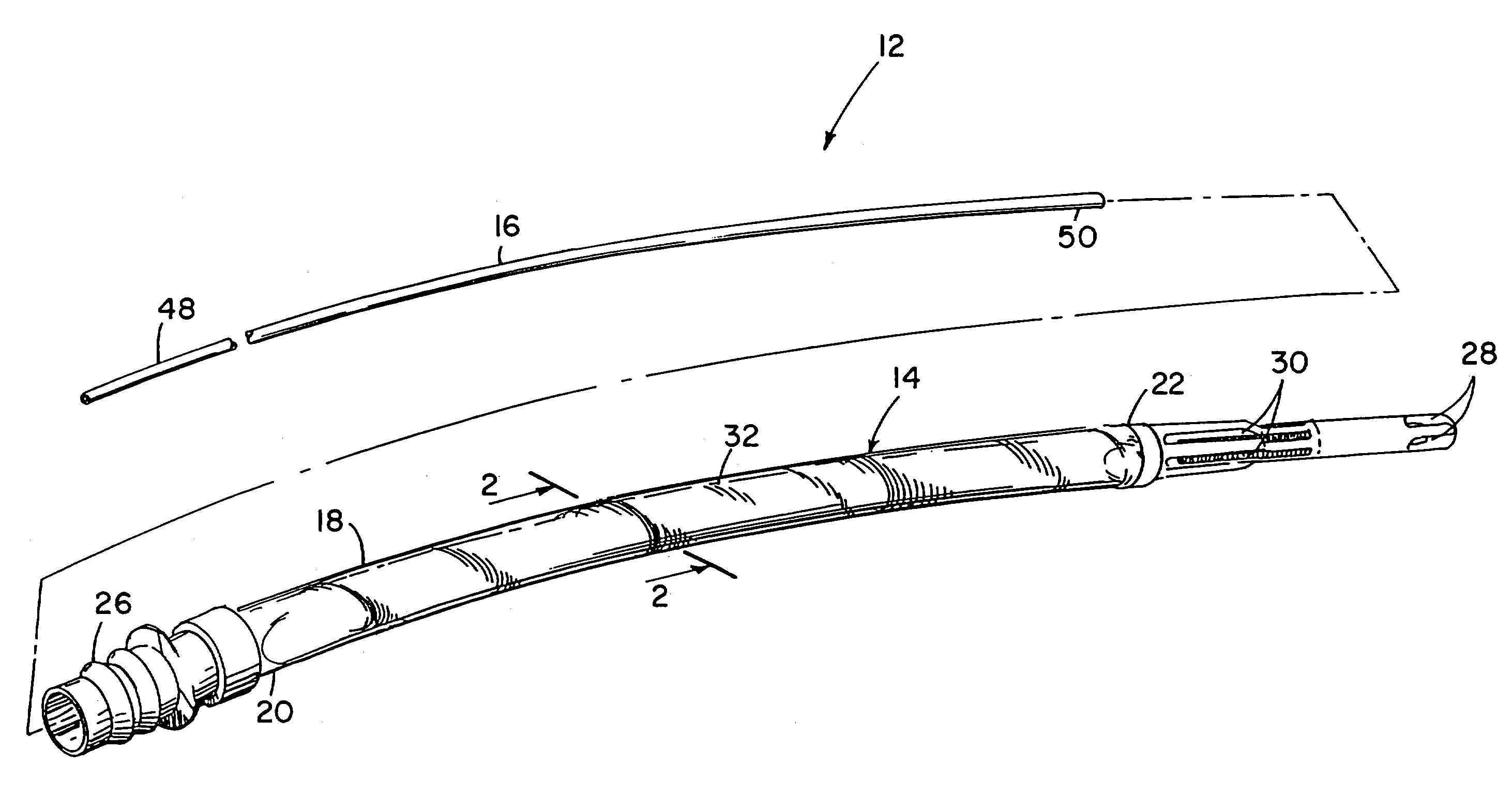
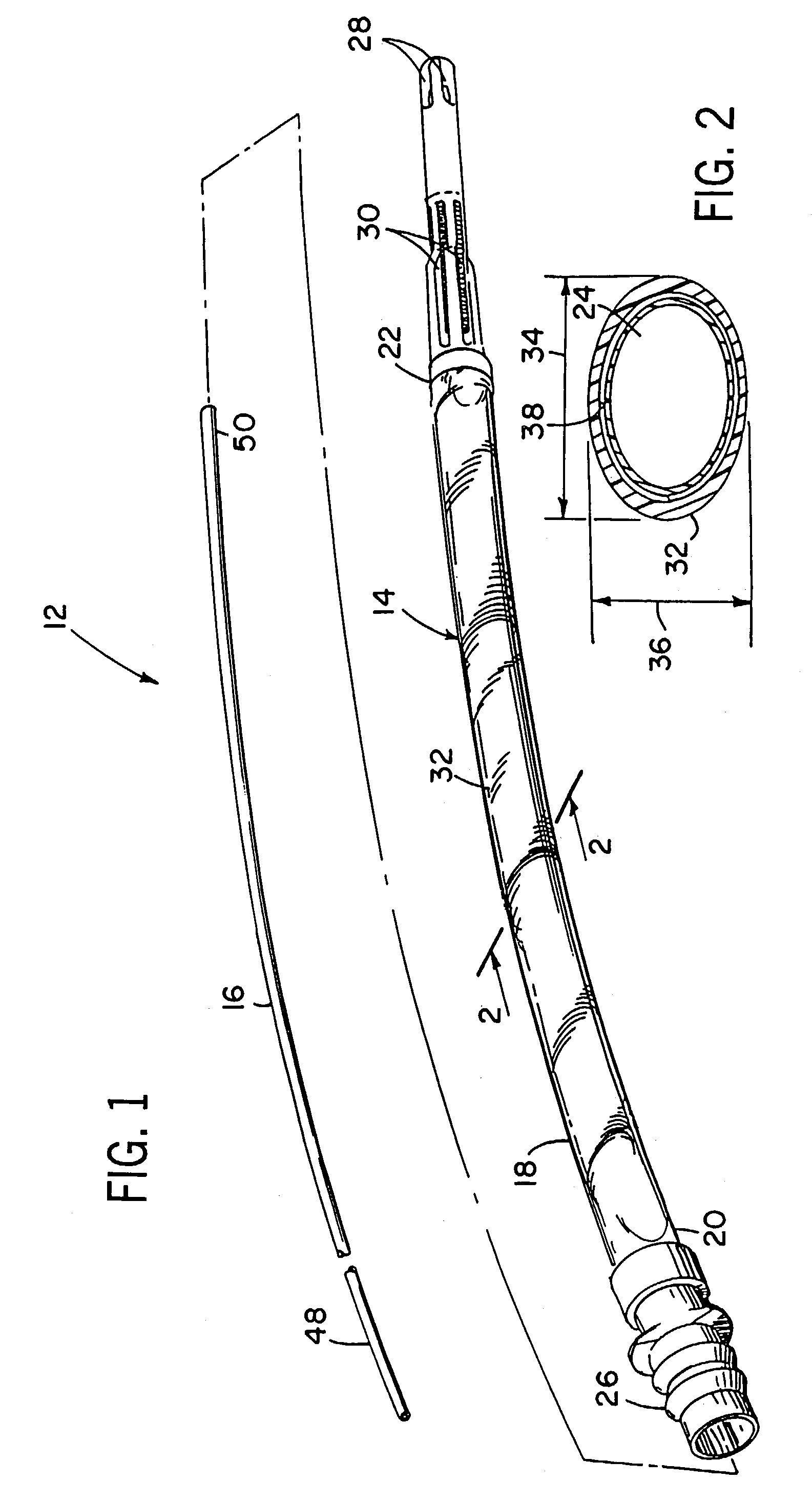
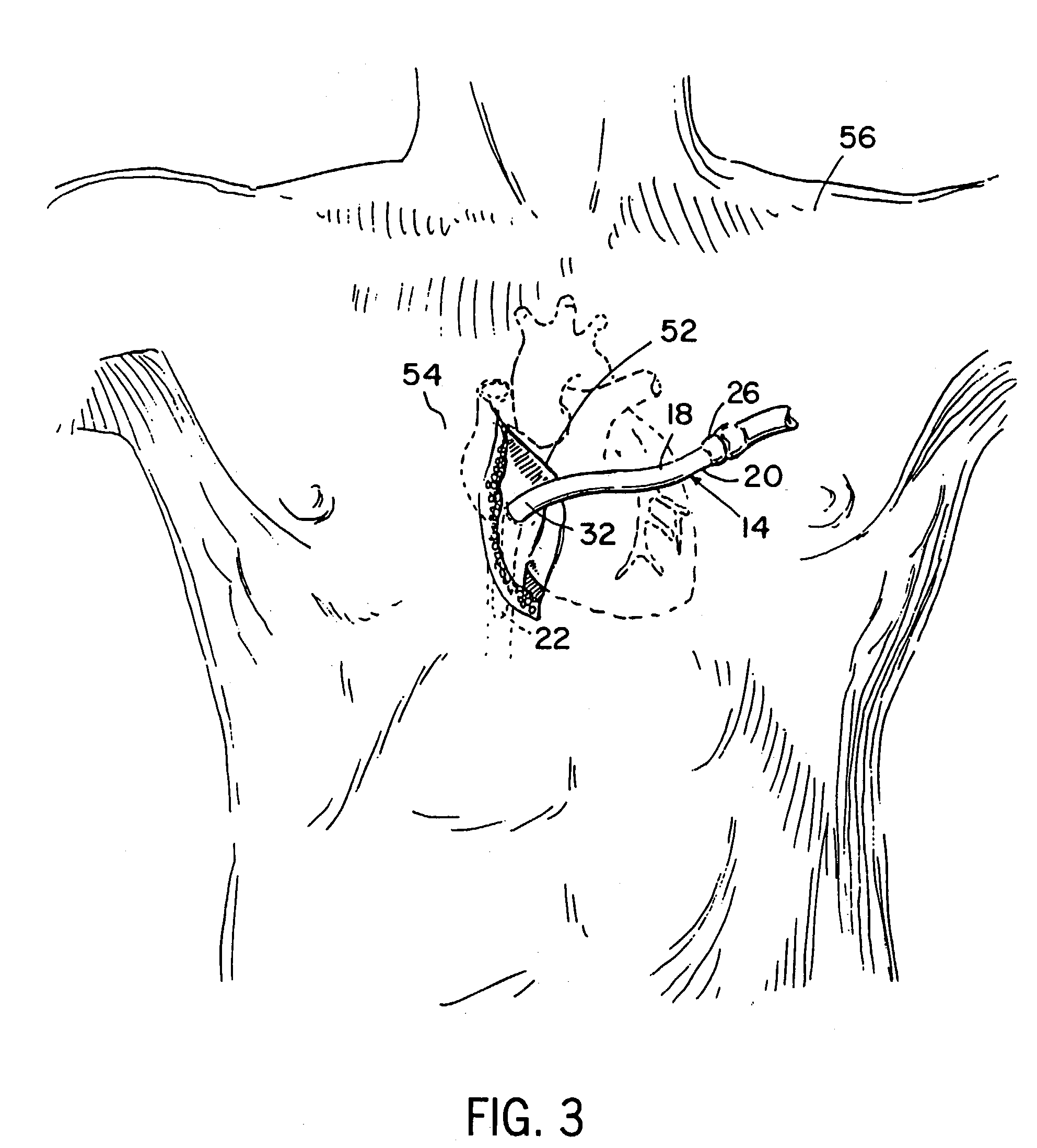
Oval-shaped cardiac cannula
a cannula and oval shape technology, applied in the field of cannulas, can solve the problems of size, geometry, space requirements of instruments, cannulas, etc., and achieve the effect of efficient occupying the space of the aperture without adversely affecting the fluid ra
- Summary
- Abstract
- Description
- Claims
- Application Information
AI Technical Summary
Benefits of technology
Problems solved by technology
Method used
Image
Examples
second embodiment
[0034]FIGS. 4 and 5 show the cannula according to the invention. In this embodiment, the cannula 64 also includes a second non-circular portion 66. Preferably, the second non-circular portion is oval in cross-section and has a major cross-sectional axis 68 and a minor cross-sectional axis 70 with the major cross-sectional axes 34, 68, respectively, of the first and second non-circular portions 32, 66 not being parallel to one another and preferably perpendicular to one another. With this structure, the first non-circular portion 32 can be positioned to extend through the access aperture 52 as described above, and the second non-circular portion 66 can be positioned either inside the body or outside the body in a particular position which requires significant bending or deflection of the cannula 64.
[0035]A second embodiment of the obturator 76 is shown in FIG. 6. When the cannula is used as a venous cannula during a cardiac surgical operation, it is preferred to include an obturator ...
third embodiment
[0037]the obturator 90 is shown in FIG. 7. Similar to the earlier embodiments, this embodiment of the obturator 90 comprises a proximal end 92 and a distal end 94. However, in this embodiment, an expandable foam member 96 is mounted on the distal end 94 of the obturator 90. In the relaxed state, the diameter of the foam member 96 is slightly larger than the interior diameter of the cannula 14 at the second set of fluid apertures 30. Therefore, when the foam member 96 is positioned immediately adjacent the apertures 30, the foam member will substantially seal the apertures 30 from the lumen 24.
[0038]In the third embodiment, the foam member 96 is formed from a soft, pliable foam which can easily be compressed by the opposed sidewalls of the cannula in the non-circular portion as the obturator 90 passes therethrough. Once the obturator 90 is fully received in the lumen 24, the foam member 96 expands outwardly a sufficient distance to substantially seal the fluid apertures 30. Similar t...
fourth embodiment
[0039]the obturator 100 for a cannula 14 is shown generally in FIGS. 8-13. As with the earlier embodiments, the obturator 100 has a proximal end 102 and a distal end 104. The obturator 100 includes an elongate member 106 and a flexible disc 108, which is coupled to the distal end 104 of the elongate member 106. The flexible disc 108 is preferably, but not necessarily, thin. In the present embodiment of the invention, the flexible disc 108 is round and has a diameter substantially equal to the diameter of the lumen 24 at the distal end 22 of the cannula body 18. However, it should be noted that the flexible disc 108 may have a non-circular shape, provided that its shape corresponds to that of the lumen 24 at the distal end 22. As illustrated in FIG. 9, when the obturator 100 is fully inserted into the cannula lumen 24, the flexible disc 108 substantially seals the distal end of the lumen 24 to prevent the flow of blood, which enters through the first set of fluid apertures 28, from p...
PUM
| Property | Measurement | Unit |
|---|---|---|
| length | aaaaa | aaaaa |
| area | aaaaa | aaaaa |
| size | aaaaa | aaaaa |
Abstract
Description
Claims
Application Information
 - R&D
- Intellectual Property
- Life Sciences
- Materials
- Tech Scout
- Unparalleled Data Quality
- Higher Quality Content
- 60% Fewer Hallucinations
Browse by: Latest US Patents, China's latest patents, Technical Efficacy Thesaurus, Application Domain, Technology Topic, Popular Technical Reports.
© 2025 PatSnap. All rights reserved.Legal|Privacy policy|Modern Slavery Act Transparency Statement|Sitemap|About US| Contact US: help@patsnap.com


