Illumination apparatus

a technology of illumination apparatus and illumination chamber, which is applied in the direction of lighting and heating apparatus, instruments, television systems, etc., can solve the problem that the illumination apparatus is not sufficient to prevent a non-uniform brightness, and achieve the effect of preventing the non-uniform brightness brought about in the irradiated region

Inactive Publication Date: 2007-10-09
FUJI PHOTO OPTICAL CO LTD
View PDF11 Cites 25 Cited by
  • Summary
  • Abstract
  • Description
  • Claims
  • Application Information

AI Technical Summary

Benefits of technology

[0016]According to the illumination apparatus of the invention, the aligning patterns or the aligning pitches of the first lens and the second lens differ from each other and therefore, light from the LED array is split into a plurality of pieces of secondary illumination light in which positions of intensity peaks differ from each other irregularly and superposed to irradiate to the irradiated region. Thereby, a nonuniformity in brightness brought about in the irradiated region can be prevented.

Problems solved by technology

However, although the apparatus described in JP-A-2003-330109 achieves an effect of preventing a drawback by the dispersion in the brightness of each LED, the apparatus is not sufficient for preventing a nonuniformity in the brightness from being brought about to the total irradiation region.

Method used


Image

  • Illumination apparatus
  • Illumination apparatus
  • Illumination apparatus

Examples


Embodiment Construction

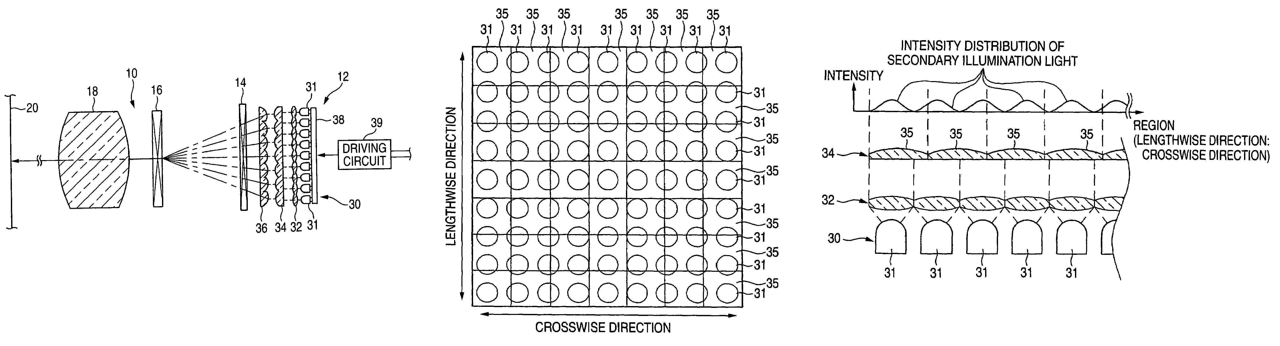
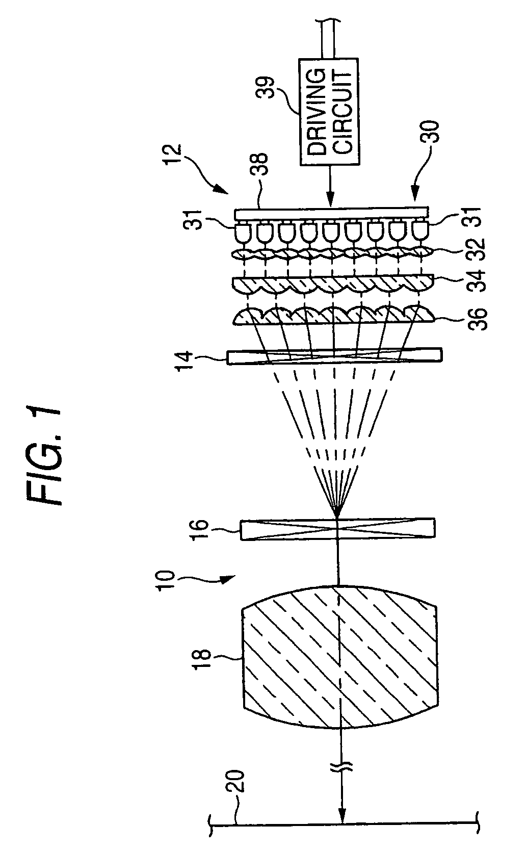
[0036]FIG. 1 shows an outline constitution view of a liquid crystal projector using an illumination apparatus of the invention. A projector 10 is provided with an illumination apparatus 12, a polarized light converting element 14, a liquid crystal panel 16, and a projection lens 18. The illumination apparatus 12 irradiates illumination light made to be uniform to a total of a rear face of the liquid crystal panel 16 although described later in details. The polarized light converting element 14 is arranged between the illumination apparatus 12 and the liquid crystal panel 16. The polarized light converting element 14 converts illumination light from the illumination apparatus into linearly polarized light.

[0037]As is well known, the liquid crystal panel 16 controls an amount of light to be transmitted by controlling a direction of aligning liquid crystals sealed between two sheets of transparent plates. By arranging color filters of R, G, B for respective pixels aligned in a matrix s...


PUM


Abstract

An illumination apparatus is provided with an LED array including a plurality of LEDs and a second lens array including a plurality of lenses. The LEDs and the lenses are arranged in lengthwise and crosswise directions and aligned such that a relationship between a number of the LEDs and a number of the lenses are mutually prime with each other in both lengthwise and crosswise directions. Primary illumination light from the LED array is split into a plurality of pieces of secondary illumination light by the lenses and thereafter superposed to irradiate. All of pieces of the secondary illumination light are provided with different strength peak positions of the illumination light and therefore, light having a uniform intensity can be irradiated to an irradiated region.

Description

[0001]This application is based on Japanese Patent application JP2004-173124, filed Jun. 10, 2004, the entire content of which is hereby incorporated by reference. This claim for priority benefit is being filed concurrently with the filing of this application.BACKGROUND OF THE INVENTION[0002]1. Technical Field of the Invention[0003]The present invention relates to an illumination apparatus using an LED array with a plurality of LEDs as a light source, particularly relates to an illumination apparatus capable of illuminating light having a uniform intensity to an illuminated region.[0004]2. Description of the Related Art[0005]There is known a liquid crystal projector for projecting image light generated by illuminating a liquid crystal panel to a screen. Although as an illumination apparatus for illuminating a liquid crystal panel, an ultra high pressure mercury lamp, a metal halide lamp or the like is used as a light source, in recent years, there is investigated to use LED capable ...

Claims


Application Information

Patent Timeline
Patent Type & Authority Patents(United States)
IPC IPC(8): F21V11/00G02B3/00F21S2/00F21V5/00F21V5/04F21V33/00F21Y101/02G03B21/00G03B21/14H04N5/74H04N9/31
CPCH04N5/74H04N9/3164H04N9/3152H04N9/315H04N5/7441
Inventor INAMOTO, MASAYUKI
Owner FUJI PHOTO OPTICAL CO LTD
Why Eureka
Try Eureka