
Lighting device, liquid crystal display device, mobile terminal device and its controlling method

Inactive Publication Date: 2006-06-15
NEC LCD TECH CORP
View PDF6 Cites 25 Cited by
  • Summary
  • Abstract
  • Description
  • Claims
  • Application Information

AI Technical Summary

Benefits of technology

[0012] Accordingly, an exemplary feature of the present invention is to reduce unevenness of luminance of a backlight caused by unevenness of luminance generated among light emitting elements that is a problem of the aforementioned conventional backlight system.
[0013] Namely, the exemplary feature of the present invention is to provide a lighting device, liquid crystal display device, mobile terminal device and its controlling method for which improvement is performed to prevent occurrence of luminance unevenness of a backlight even if there is a capability difference between driving sections that drive individual light emitting elements (for example, LEDs).
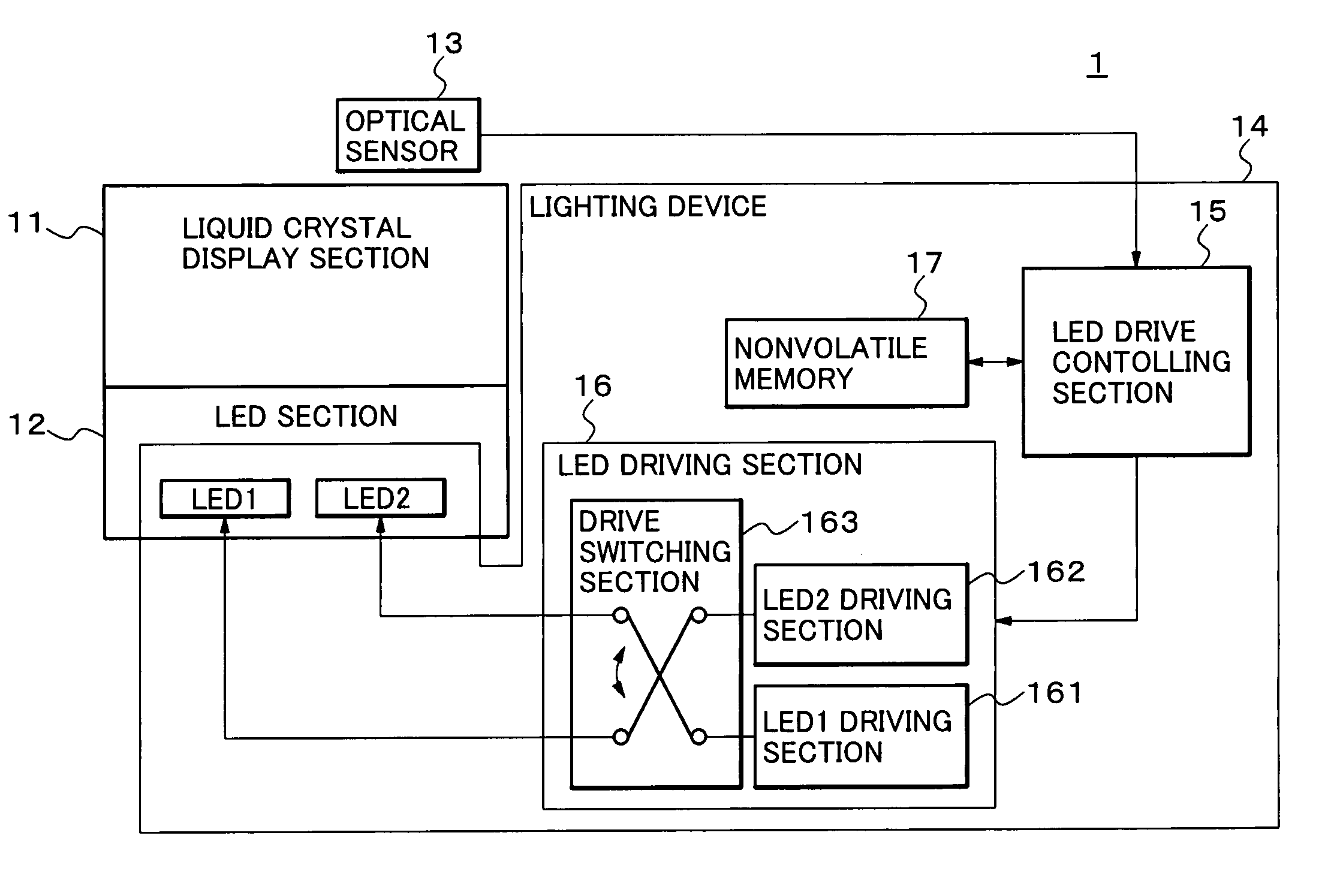
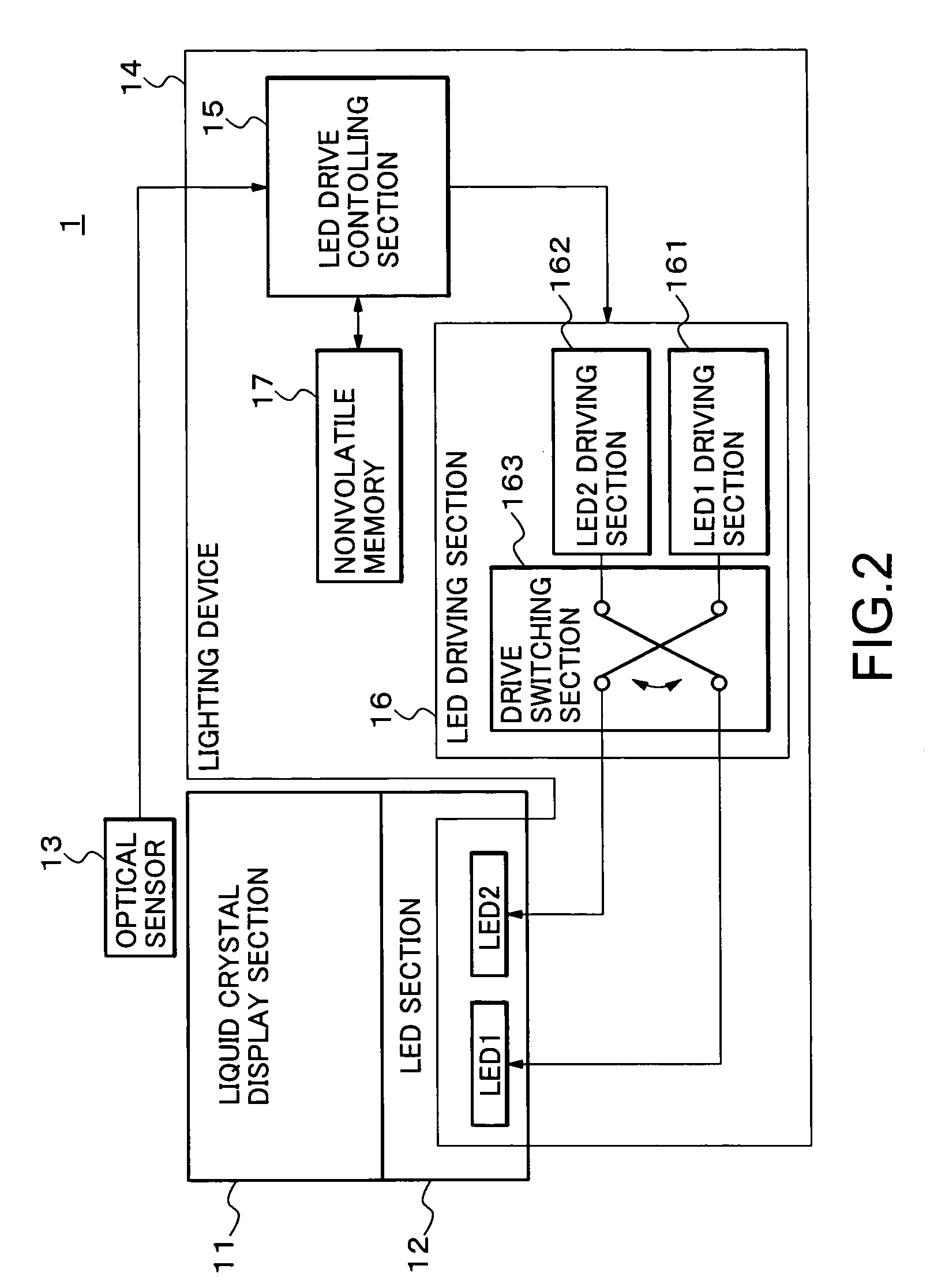
[0035] According to the lighting device of the present invention, the drive switching section alternately switches the drive of the plurality of light emitting elements using the plurality of driving sections at every fixed cycle. This drives the plurality of light emitting elements equally to make it possible to equalize luminance of plural light emitting elements even if there is a difference in drive capability among the plural driving sections.
[0036] According to the liquid crystal display device of the present invention,. the drive switching section of the lighting device alternately switches the drive of the plurality of light emitting elements using the plurality of driving sections at every fixed cycle. This drives the plurality of light emitting elements equally to make it possible to equalize luminance of plural light emitting elements even if there is a difference in drive capability among the plural driving sections. Accordingly, it is possible to reduce the unevenness of the display image resulting from the lighting device.
[0037] According to the mobile terminal device of the present invention, the drive switching section of the lighting device alternately switches the drive of the plurality of light emitting elements using the plurality of driving sections at every fixed cycle. This drives the plurality of light emitting elements equally to make it possible to equalize luminance of plural light emitting elements even if there is a difference in drive capability among the plural driving sections. Accordingly, it is possible to reduce the unevenness of the display image resulting from the lighting device.
[0038] According to the lighting device controlling method of the present invention, the plurality of light emitting elements and the plurality of driving sections are alternately switched to be connected to each other and to detect light of lit by the light emitting elements, so that the switching of the emission of light emitting elements is controlled based on the detection result. This drives the plurality of light emitting elements equally to make it possible to equalize luminance of plural light emitting elements even if there is a difference in drive capability among the plural driving sections.

Problems solved by technology

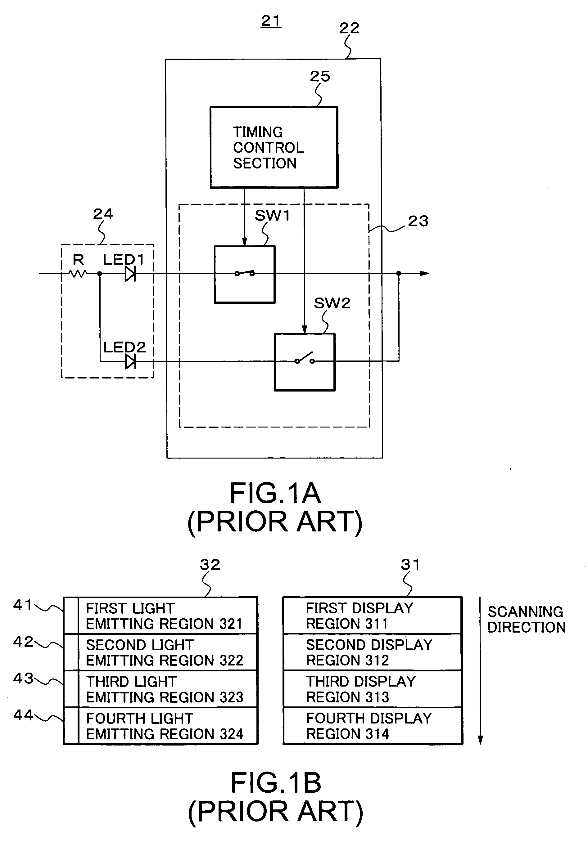
However, this document does not disclose anything about its improving method.
Meanwhile, in Japanese Patent No. 3584351, it is described that unevenness of luminance occurs since the scanning start region and the scanning end region are different from each other in light transmittance due to the characteristic problem of the liquid crystal panel itself even if the same voltage is applied thereto.
However, this does not take measures against the unevenness of luminance in each divided light emitting region, resulting in difficulty to provide light emission intensity to each light emitting region in details.

Method used


Image

  • Lighting device, liquid crystal display device, mobile terminal device and its controlling method
  • Lighting device, liquid crystal display device, mobile terminal device and its controlling method
  • Lighting device, liquid crystal display device, mobile terminal device and its controlling method

Examples


first embodiment

[0063] A specific operation will be explained with reference to FIG. 3 and FIG. 4 that shows a timing chart for explaining the operation in the

[0064] First of all, it is assumed that switch S1-1 is in a high level (hereinafter referred to as on state) of a logical level, switch S1-2 is in a low level (hereinafter referred to as off state) , switch S2-1 is in an off state, and the switch S1-2 is in an on state. The driving current (R output) inputted to the switch S1 from the LED1-R driving section is divided into the switches S1-1 and S1-2 respectively and supplied thereto as a common input. It is assumed that drive capability of the driving current (R output) supplied at this time is a P value.

[0065] The PWM output is in an on state until timing T1 and the switch S1-1 is also in an on state, so that the R output drives the LED1-R from the first output terminal using a high-level P value accordingly.

[0066] Meanwhile, the R output inputted to the switch S2 from the LED2-R driving s...

second embodiment

[0085] A specific operation will be explained with reference to FIG. 5 and FIG. 6 that shows a timing chart for explaining the operation in the The switches S1-1, S1-2, and S1-3 of the switch S1 are respectively controlled in synchronization with the PWM signal by the switch signal from the switch signal generating section 164 in such a manner that these switches are turned on independently of one another without being turned on simultaneously. Similarly, the switches S2 and S3 are also respectively controlled in such a manner that these switches are turned on independently of one another without being turned on simultaneously. Moreover, regarding the switches with the same number among the switches S1, S2 and S3, for example, two or more switches of S1-1, S1-2 and S1-3 are controlled not to be turned on simultaneously.

[0086] First, the PWM output is in an on state until timing T1 and the switch S1-1 of the switch S1 is in an on state and other switches S1-2 and S1-3 are in an off ...


PUM


Abstract

A lighting device of backlight type that transmits light of a plurality of light emitting elements from a display section includes a plurality of driving sections that drive the plurality of light emitting elements; and drive switching section, provided between the plurality of driving sections and the plurality of light emitting elements, for switching the drive of the plurality of light emitting elements alternately at every fixed cycle.

Description

BACKGROUND OF THE INVENTION [0001] 1. Field of the Invention [0002] The present invention relates to a lighting device, liquid crystal display device, mobile terminal device and its controlling method, and more particularly relates to a lighting device, liquid crystal display device, mobile terminal device and its controlling method by which unevenness of luminance is improved when light emitting elements as backlight are lit. [0003] 2. Description of the Related Art [0004] A liquid display device needs an external light source since the liquid display device itself is not a self-luminous display device. A backlight in a lighting device generally refers to a light source provided on a back surface of the liquid crystal display. Especially, in a transmissive liquid crystal display device, the light source is placed on the back surface. For this reason, this light source is referred to as the backlight. [0005] Conventionally, a cold cathode tube is mainly used as a backlight source. T...

Claims


Application Information

Patent Timeline
IPC IPC(8): G09G3/36
CPCG09G3/342G09G2320/0233G09G2320/064G09G2360/145
Inventor NISHIGAKI, EITARO
Owner NEC LCD TECH CORP
Learn More