Planar light source device and display device

a light source device and display device technology, applied in the direction of planar/plate-like light guides, lighting and heating apparatus, instruments, etc., can solve the problems of brightness irregularity in luminance, difficult to provide a high quality image with a smooth change, etc., to secure restrain brightness irregularity

Active Publication Date: 2010-03-25
SATURN LICENSING LLC
View PDF1 Cites 25 Cited by
  • Summary
  • Abstract
  • Description
  • Claims
  • Application Information

AI Technical Summary

Benefits of technology

[0017]According to the present invention, it is possible to provide a planar light source device and display device that can securely restrain the brightness irregularity, when changing the luminance of a display screen in the unit of a plurality of blocks.

Problems solved by technology

This results in an issue of brightness irregularity in the luminance.
Therefore, it is difficult to provide a high quality image with a smooth change in contrast of the brightness in the entire display screen.

Method used


Image

  • Planar light source device and display device
  • Planar light source device and display device
  • Planar light source device and display device

Examples


Embodiment Construction

[0038]Hereinafter, preferred embodiments of the present invention will be described in detail with reference to the appended drawings. Note that, in this specification and the appended drawings, structural elements that have substantially the same function and structure are denoted with the same reference numerals, and repeated explanation of these structural elements is omitted. The descriptions will be made in the following order.

[0039]1. Configuration of a display device according to an embodiment of the present invention

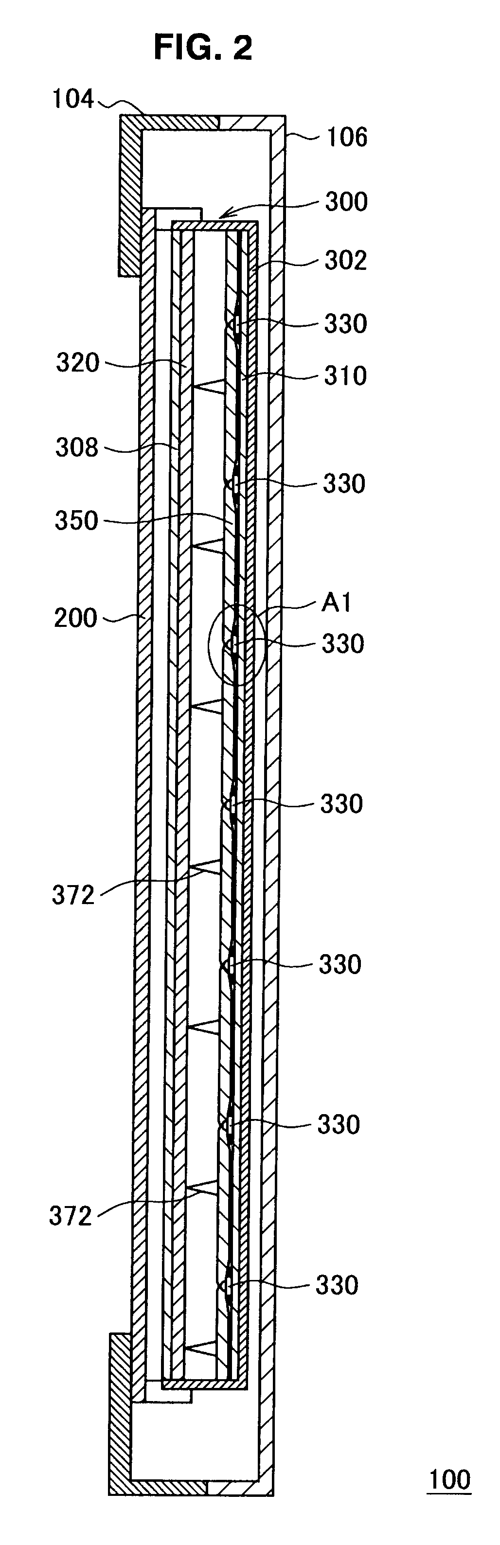
[0040]2. Configuration of the surrounding of the light-emitting diode

[0041]3. Configuration of a light guide plate

[0042]4. Configuration of a light guide member

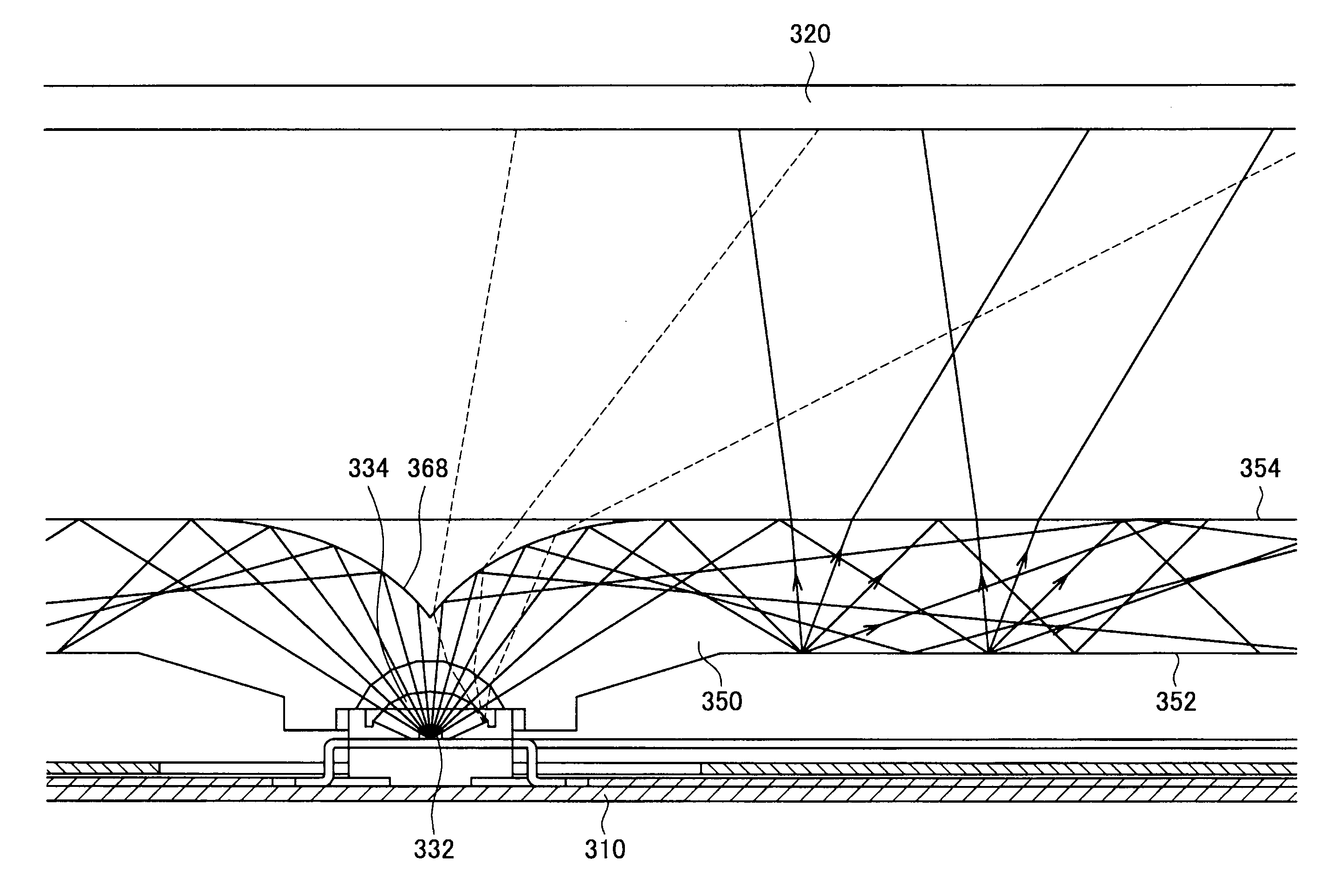
[0043]5. Effect of light diffusion by a light guide member of this embodiment

[0044]6. About area for forming an emission facilitating surface

[1. Entire Configuration of Display Device According to Embodiment of Present Invention]

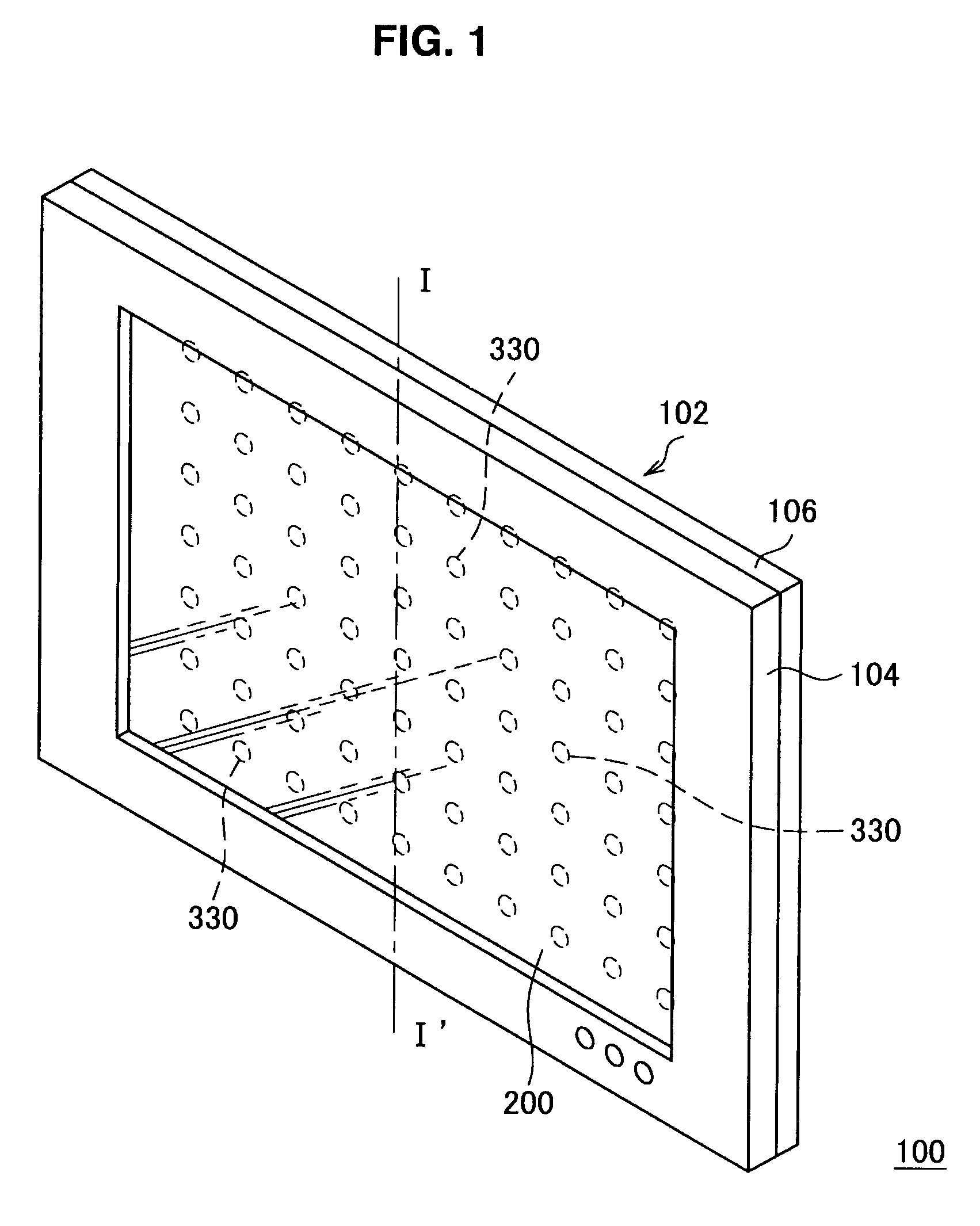
[0045]FIG. 1 is a perspective diagram showing a configuration of an image disp...


PUM


Abstract

A planar light source device of the present invention includes a light guide plate and a plurality of light-emitting diodes. The light guide plate includes a plurality of plate-form light guide members whose side surfaces are formed in a serrated shape. The serrated-shaped side surfaces of adjacent light guide members are connected in a planar direction so as to be engaged with each other. The plurality of light-emitting diodes emit light toward each of the light guide members. With this configuration, it is possible to securely prevent irregularity of brightness, when changing the luminance in the display screen in unit of blocks.

Description

BACKGROUND OF THE INVENTION[0001]1. Field of the Invention[0002]The present invention relates to a planar light source device and a display device.[0003]2. Description of the Related Art[0004]In the past, there is a known planar light source device, as shown in JP-A No. 2007-206398. This planar light source device has an object of lightning the effect of a luminance decrease in accordance with the boundary of light guide blocks on a light diffusion plate of a display device.[0005]As disclosed in JP-A No. 2005-17324 and JP-A No. 1999-109317, according to a known technique, a display screen is divided into a plurality of blocks, the backlight luminance is changed in the unit of divided blocks in accordance with an input image signal. JP-A No. 2005-17324 and JP-A No. 1999-109317 suggest for low consumption power and for expanding the dynamic range of a display luminance, by changing the backlight luminance in accordance with an input image signal.SUMMARY OF THE INVENTION[0006]However, ...

Claims


Application Information

Patent Timeline
Patent Type & Authority Applications(United States)
IPC IPC(8): F21V8/00
CPCG02B6/0016G02B6/0018G02B6/0021G02F1/133611G02B6/0073G02B6/0078G02F1/133603G02B6/0068
Inventor OHKAWA, SHINGO
Owner SATURN LICENSING LLC
Why Eureka
Try Eureka