Systems, methods and apparatus for X-ray tube housing

a technology of x-ray tube and x-ray tube, which is applied in the cooling of x-ray tube, electric discharge tube, basic electric elements, etc., can solve the problems of increased weight and power requirements at the x-ray tube, limited amount of time needed to image a subject, and high fixed cost of x-ray imaging devices that the owners and operators of x-ray imaging devices hav

Active Publication Date: 2007-10-09
GENERAL ELECTRIC CO
View PDF3 Cites 14 Cited by
  • Summary
  • Abstract
  • Description
  • Claims
  • Application Information

AI Technical Summary

Problems solved by technology

X-ray imaging devices have a high fixed cost that the owners and operators of the X-ray imaging devices seek to either reduce and / or the owners and operators seek to derive the greatest amount of productivity from the devices, in order to obtain the greatest return-on-investment from the X-ray imaging device.
However, the amount of time needed to image a subject is limited to some extent by the amount of time that is required in between imaging sessions to cool the X-ray tube that is in the X-ray imaging device.
Existing cooling solutions have resulted in increased weight and power requirements at the X-ray tube.
Any increased weight at the X-ray tube is particularly undesirable due to the counter balancing required for the gantry, and the use of a fan restricts use of the system in some surgical environments.
Conventional X-ray tube housings require a complex design with many parts to integrate the secondary plumbing and customized cooling solutions within the X-ray tube housing which result in high manufacturing and assembly costs.

Method used


Image

  • Systems, methods and apparatus for X-ray tube housing
  • Systems, methods and apparatus for X-ray tube housing
  • Systems, methods and apparatus for X-ray tube housing

Examples


Embodiment Construction

[0023]In the following detailed description, reference is made to the accompanying drawings that form a part hereof, and in which is shown by way of illustration specific embodiments which may be practiced. These embodiments are described in sufficient detail to enable those skilled in the art to practice the embodiments, and it is to be understood that other embodiments may be utilized and that logical, mechanical, electrical, and other changes may be made without departing from the scope of the embodiments. The following detailed description is, therefore, not to be taken in a limiting sense.

[0024]The detailed description is divided into four sections. In the first section, a system level overview is described. In the second section, apparatus of embodiments are described. In the third section, embodiments of methods are described. Finally, in the fourth section, a conclusion of the detailed description is provided.

System Level Overview

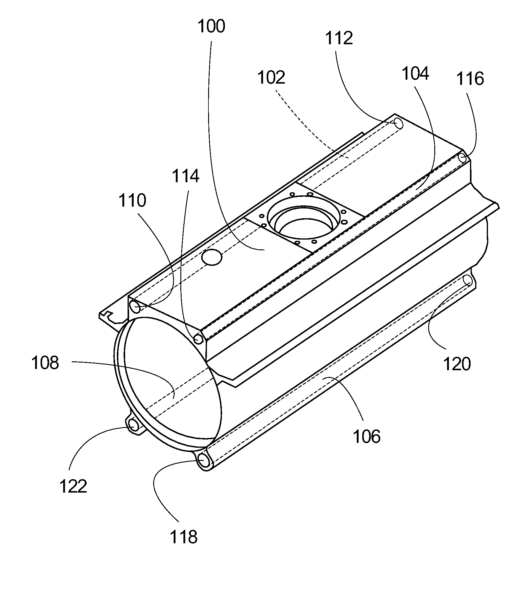
[0025]FIG. 1 is an overview diagram of an ill...


PUM


Abstract

An X-ray tube housing with integrated cooling passages in the walls of the X-ray tube housing, through which a liquid or gas coolant is circulated and the heat is transferred from the X-ray tube housing to an external cooler. The integrated cooling passages are created around the perimeter of the X-ray tube housing as the X-ray tube housing is formed. For a rotating anode X-ray tube using an oil coolant, the path of heat transfer is from the anode to the glass insert and oil by the means of radiation. The oil that is in contact with the glass insert conducts heat away form the insert to the X-ray tube housing which is then cooled by the integrated cooling passages located within the X-ray tube housing through which fluid is passed to an external fluid cooling system.

Description

FIELD OF THE INVENTION[0001]This invention relates generally to medical imaging systems, and more particularly to cooling of portable of medical imaging devices.BACKGROUND OF THE INVENTION[0002]Through-put and turnaround of patients is a key economic metric of the productivity of X-ray imaging devices. X-ray imaging devices have a high fixed cost that the owners and operators of the X-ray imaging devices seek to either reduce and / or the owners and operators seek to derive the greatest amount of productivity from the devices, in order to obtain the greatest return-on-investment from the X-ray imaging device.[0003]One way to derive the greatest amount of productivity from the X-ray imaging device is to increase the number of subjects or patients that are imaged in an amount of time. However, the amount of time needed to image a subject is limited to some extent by the amount of time that is required in between imaging sessions to cool the X-ray tube that is in the X-ray imaging device...

Claims


Application Information

Patent Timeline
Patent Type & Authority Patents(United States)
IPC IPC(8): H01J35/10
CPCH01J35/16H05G1/025H01J2235/1262H01J2235/1216
Inventor WEAVER, GREGORY ALANWESTON, LONNIE B.BARKER, DAVID ELLIS
Owner GENERAL ELECTRIC CO
Why Eureka
Try Eureka