
Roofing shingle

a technology of roofing shingles and roofing panels, applied in the direction of roofing, construction, building components, etc., can solve the problems of hazard to roofers walking on the roof, slippery loose felt paper sheets, and deterioration of asphalt shingles, so as to achieve safe and easy installation

Inactive Publication Date: 2007-10-16
FLOYD CHARLES T
View PDF19 Cites 24 Cited by
  • Summary
  • Abstract
  • Description
  • Claims
  • Application Information

AI Technical Summary

Benefits of technology

[0006]Accordingly, it is an object of the invention to provide a composite shingle for roofing systems having a backing material affixed to the back side of each shingle for safe and easy installation.
[0010]It is another object of the invention to provide a roofing system made with integral composite shingles having a backing material affixed to the back side of each shingle for safe and easy installation.

Problems solved by technology

In particular, asphalt shingles will deteriorate due to heat damage if no backing material, such as felt paper, is positioned between roofing shingles and the roof surface.
However, the loose felt paper sheets are slippery and present a hazard to roofers walking thereon during shingle installation.
Also, multiple steps of applying the felt paper first and secondarily applying shingles thereover, requires additional time and cost.
The prior art has attempted to attach a felt backing on individual shingles, but problems associated with the attachment of the felt were introduced thereby.

Method used


Image

  • Roofing shingle
  • Roofing shingle
  • Roofing shingle

Examples


Embodiment Construction

[0035]In the following description, like reference characters designate like or corresponding parts throughout the several views. Also, in the following description, it is to be understood that such terms as “forward,”“rearward,”“front,”“back,”“right,”“left,”“downwardly,” and the like are words of convenience and are not to be construed as limiting terms.

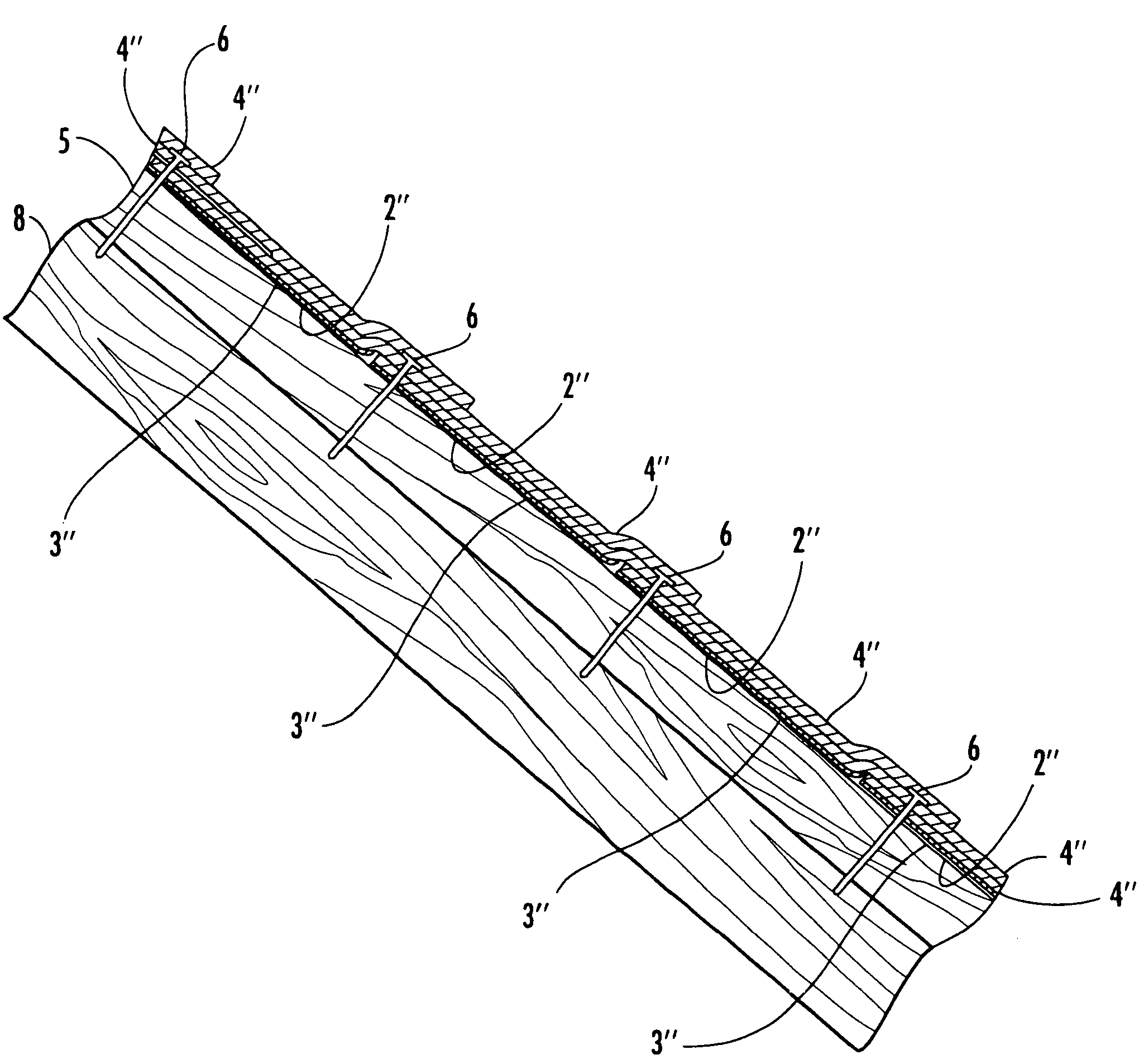
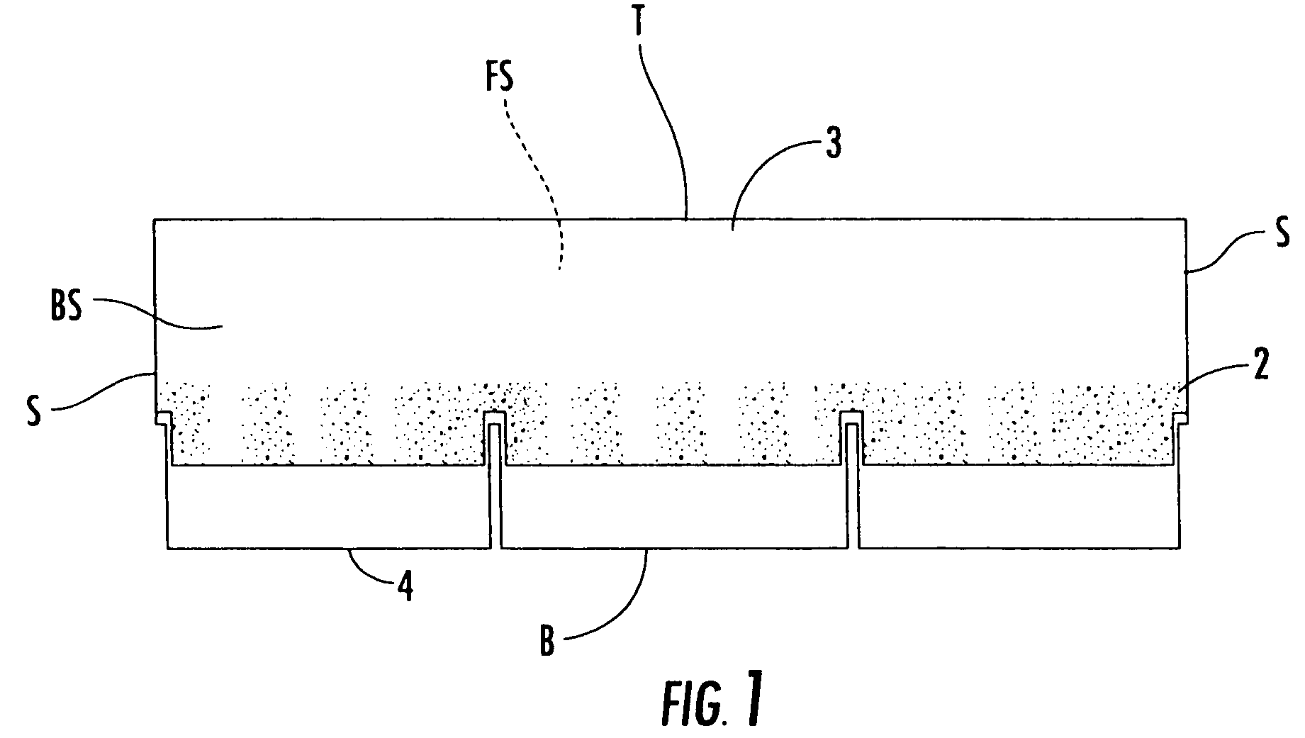
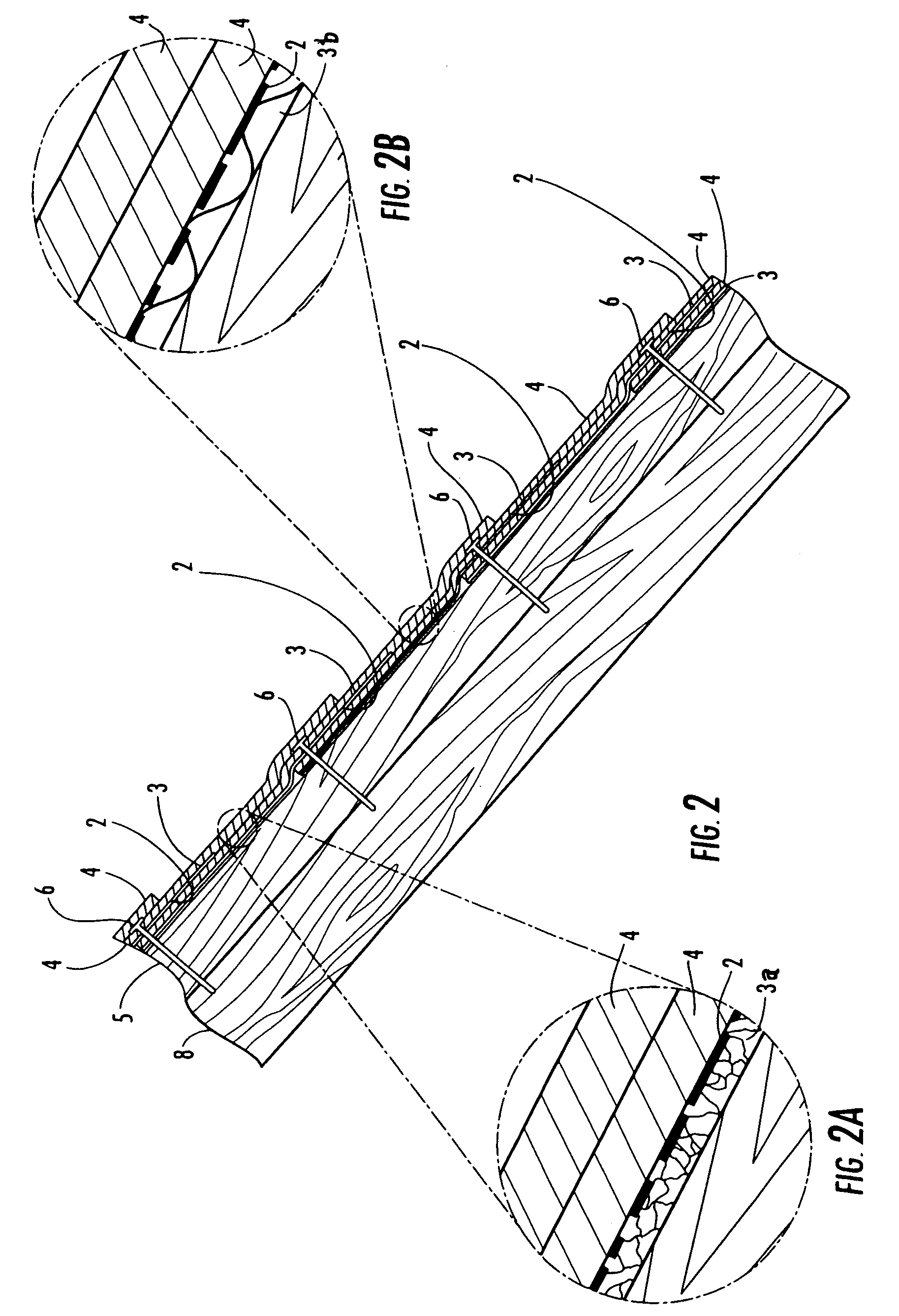
[0036]Referring now to the drawings in general, the illustrations are for the purpose of describing the invention and are not intended to limit the invention thereto. FIG. 1 illustrates a back side view of a roofing shingle body including a face side “FS” and a back side “BS”, spaced-apart top and bottom edges “T” and “B” respectively, and two spaced-apart side edges “S”. In the illustrated example, the shingle 4 includes three tabs located adjacent to the bottom edge B. The number of tabs may be varied to suit a particular application. Some shingles may have a single continuous section which has simulated tabs, but no actual separa...


PUM


Abstract

A roofing system having shingles. The shingles include a front side, a back side, a pair of spaced-apart side edges, and spaced-apart top and bottom edges, an adhesive, and a backing material. The adhesive is applied to a portion of the shingle for affixing the backing material to the shingle and covering a portion of the back side.

Description

[0001]This application claims the benefit of Provisional Application No. 60 / 601,822 filed on Aug. 16, 2004.TECHNICAL FIELD AND BACKGROUND OF THE INVENTION[0002]The present invention relates generally to roofing systems and, more particularly, to a roofing system having composite shingles.[0003]Typically, prior art sloped roofing systems include a layer of loose felt paper that covers the roof to prevent shingle heat damage and deterioration where shingles contact each other or the roof underlayment directly. In particular, asphalt shingles will deteriorate due to heat damage if no backing material, such as felt paper, is positioned between roofing shingles and the roof surface. However, the loose felt paper sheets are slippery and present a hazard to roofers walking thereon during shingle installation. Also, multiple steps of applying the felt paper first and secondarily applying shingles thereover, requires additional time and cost.[0004]The prior art has attempted to attach a felt...

Claims


Application Information

Patent Timeline
Patent Type & Authority Patents(United States)
IPC IPC(8): E04D1/00
CPCE04D1/26
Inventor FLOYD, CHARLES T.
Owner FLOYD CHARLES T
Learn More