Optical module and connecting construction for optical module

Inactive Publication Date: 2005-01-11
KYOCERA CORP
View PDF10 Cites 10 Cited by
  • Summary
  • Abstract
  • Description
  • Claims
  • Application Information

AI Technical Summary

Benefits of technology

With these construction, it may be possible to first mount the connector on an electric circuit board, and thereafter mount the optical module having the light transmitter or optical fiber. Accordingly, the optical module can be mounted on the electric circuit board

Problems solved by technology

In the optical modules of pigtail type, an optical fiber having a covering portion is present in the module and this covering portion not resistant to heat may be deteriorated.
Accordingly, it is difficult to mount the optical module together with other parts on an electric circuit board in one step by reflow soldering.
Such assembling operation is very cumbersome if a multitude of optical modules are necessary.
Further, with optical modules of receptacle type, it is difficult to arrange external optical fiber cord connected with an optical module in vicinity of a light emitting element, thereby necessitating an optical part such as a lens.
This disadvantageously stands as a h

Method used


Image

  • Optical module and connecting construction for optical module
  • Optical module and connecting construction for optical module
  • Optical module and connecting construction for optical module

Examples


Embodiment Construction

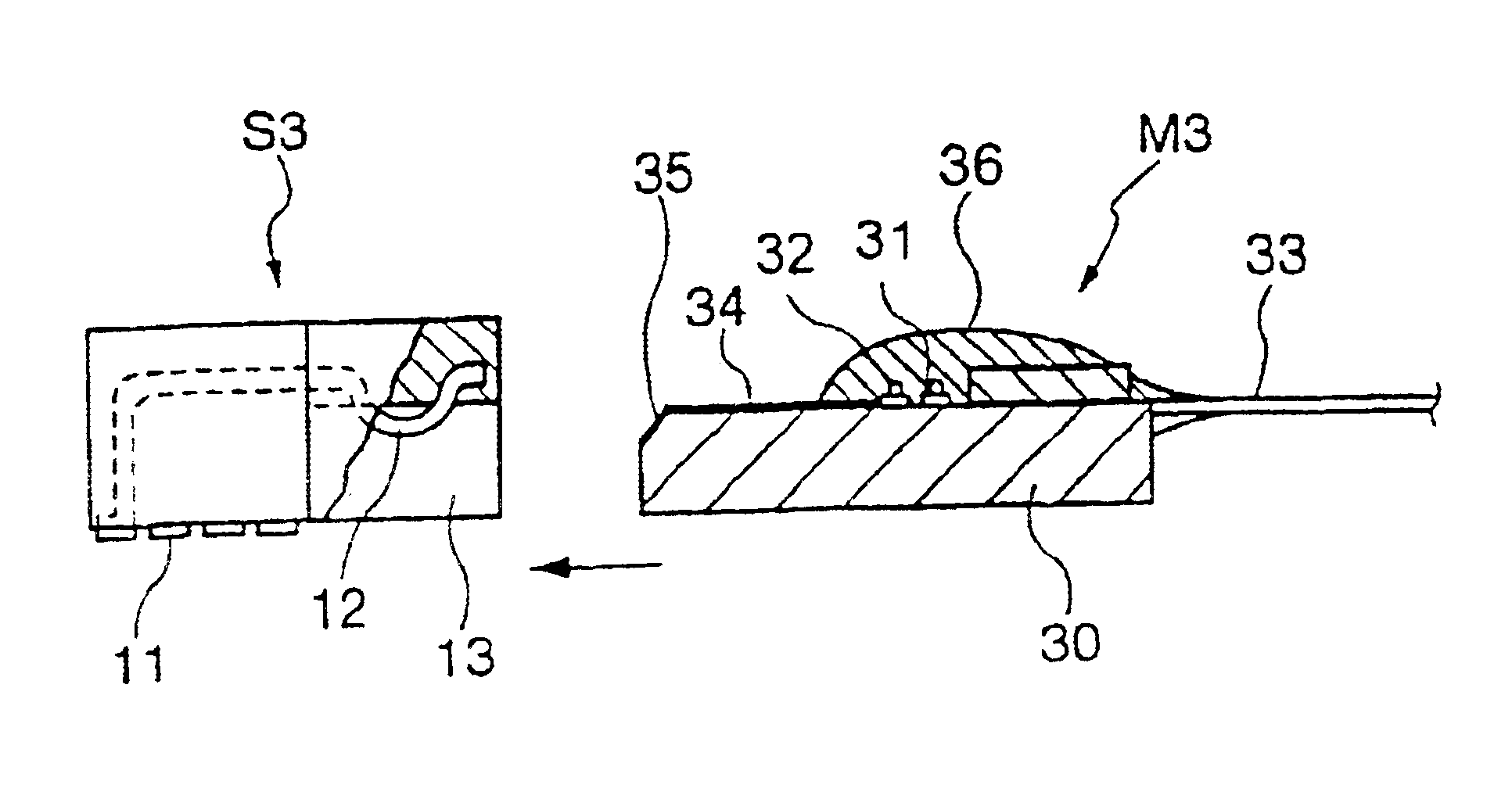
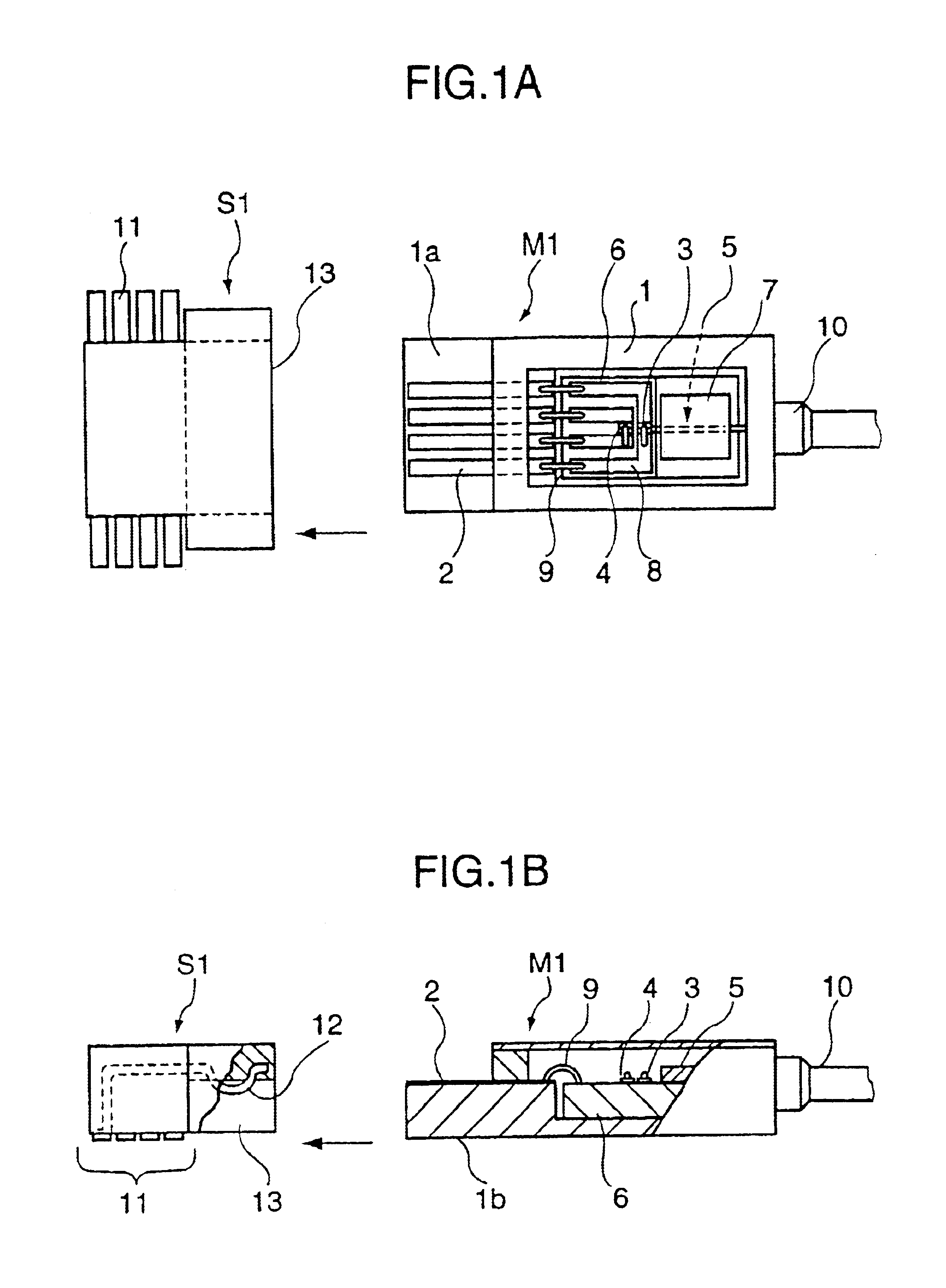
FIGS. 1A and 1B show a card type optical module M1 and a socket S1 for,connecting the optical module M1. A lid provided on a top surface of the optical module M1 is not shown in FIG. 1A, and the optical module M1 and the socket S1 which serves as a connector portion are shown partly in section in FIG. 1B. It is assumed that the socket S1 is mounted on a circuit board.

The optical module M1 is fabricated as follows: connection terminals 2 formed of copper wires are provided at one end 1a of a package 1 which is a flat base made of ceramic or like material, and optical elements connected with the connection terminals 2. The optical elements include a light emitting element 3 such as a semiconductor laser, a light receiving element 4 such as a photodiode for monitoring the light emitting element 3, and an optical fiber 5 serving as slender light transmitter having one end optically coupled to the light emitting element 3. They are arranged on a substrate 6. Further, an optical fiber cor...


PUM


Abstract

An optical module includes a flat substrate, an electric connection terminal provided on the substrate, an optical element provided on the substrate, the optical element being connected with the electric connection terminal, and one end of a slender light transmitted fixed on the substrate and optically coupled with the optical element. The electric connection terminal is connectable with an external connector. The connector (or socket) is first mounted on an electric circuit board by reflow soldering or the like, and then the optical module having the slender light transmitter (or optical fiber) is electrically connected with the connector.

Description

BACKGROUND OF THE INVENTIONThis invention relates to an optical module and a connecting construction for an optical module which are used mainly in an optical communication equipment or the like.Conventional optical modules can be roughly classified into those of pigtail type in which a module main body is provided with a pigtail cord which is connected with an external optical fiber cord by a connector, and those of receptacle type in which an external optical fiber cord is directly connected with an adapter of a module main body.In the optical modules of pigtail type, an optical fiber having a covering portion is present in the module and this covering portion not resistant to heat may be deteriorated. Accordingly, it is difficult to mount the optical module together with other parts on an electric circuit board in one step by reflow soldering. For this reason, the following manufacturing operations have been conventionally carried out. Heat-resistant parts are mounted on an elect...

Claims


Application Information

Patent Timeline
IPC IPC(8): G02B6/42
CPCG02B6/4292G02B6/4201
Inventor KUBA, YUTAKA
Owner KYOCERA CORP
Why Eureka
Try Eureka