Air treatment system

Active Publication Date: 2015-10-01
ACCESS BUSINESS GRP INT LLC
View PDF9 Cites 10 Cited by
  • Summary
  • Abstract
  • Description
  • Claims
  • Application Information

AI Technical Summary

Benefits of technology

[0006]The present invention provides an air treatment system having an improved control system. In one embodiment, the control system includes a “dead front” display that provides the ATS with a clean and simple appearance, and that facilitates an improved control experience. The display may include a plurality of informative display elements and a plurality of touch sensors that are selectively illuminated by an underlying arrangement of light sources, such as LEDs. To produce the desired graphics, each light source may be

Problems solved by technology

Air treatment systems continue to grow in popularity as concerns about air quality remain an issue of significant concern.
Conventional particulate filters and carbon filters have a limited life and require occasional replacement.
The structure of the air

Method used


Image

  • Air treatment system
  • Air treatment system
  • Air treatment system

Examples


Embodiment Construction

A. Overview

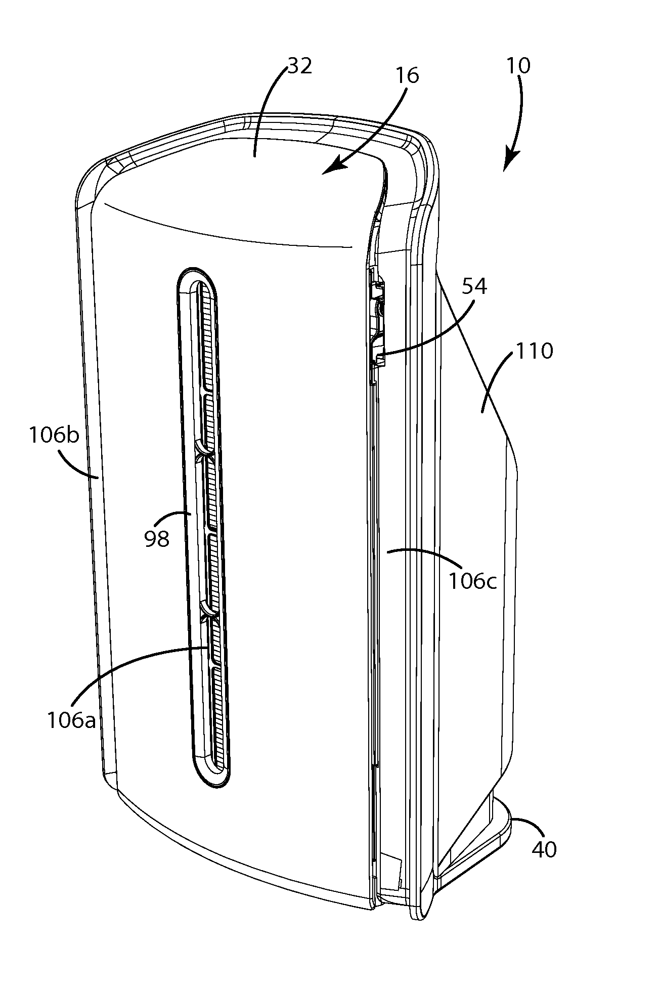
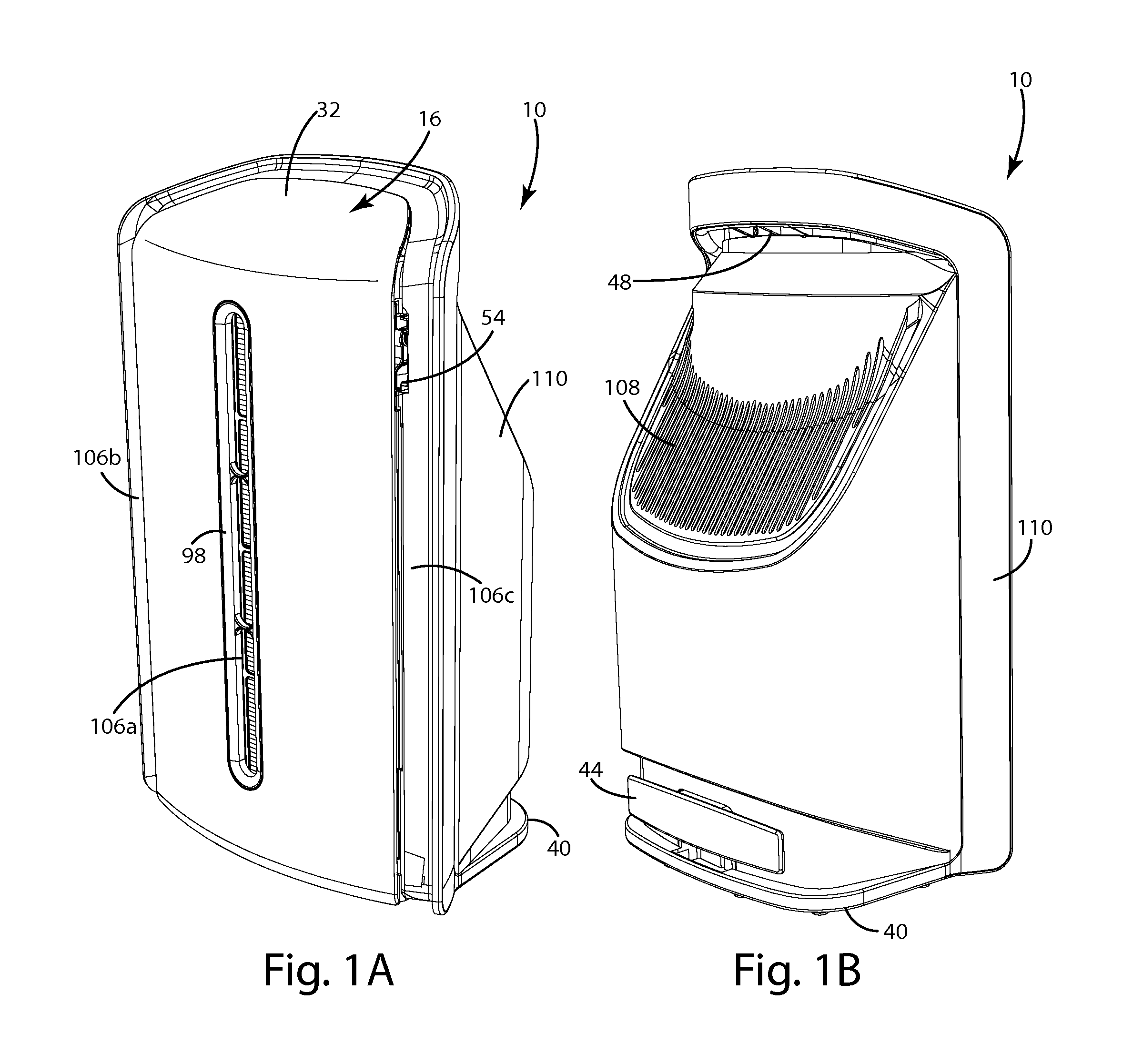
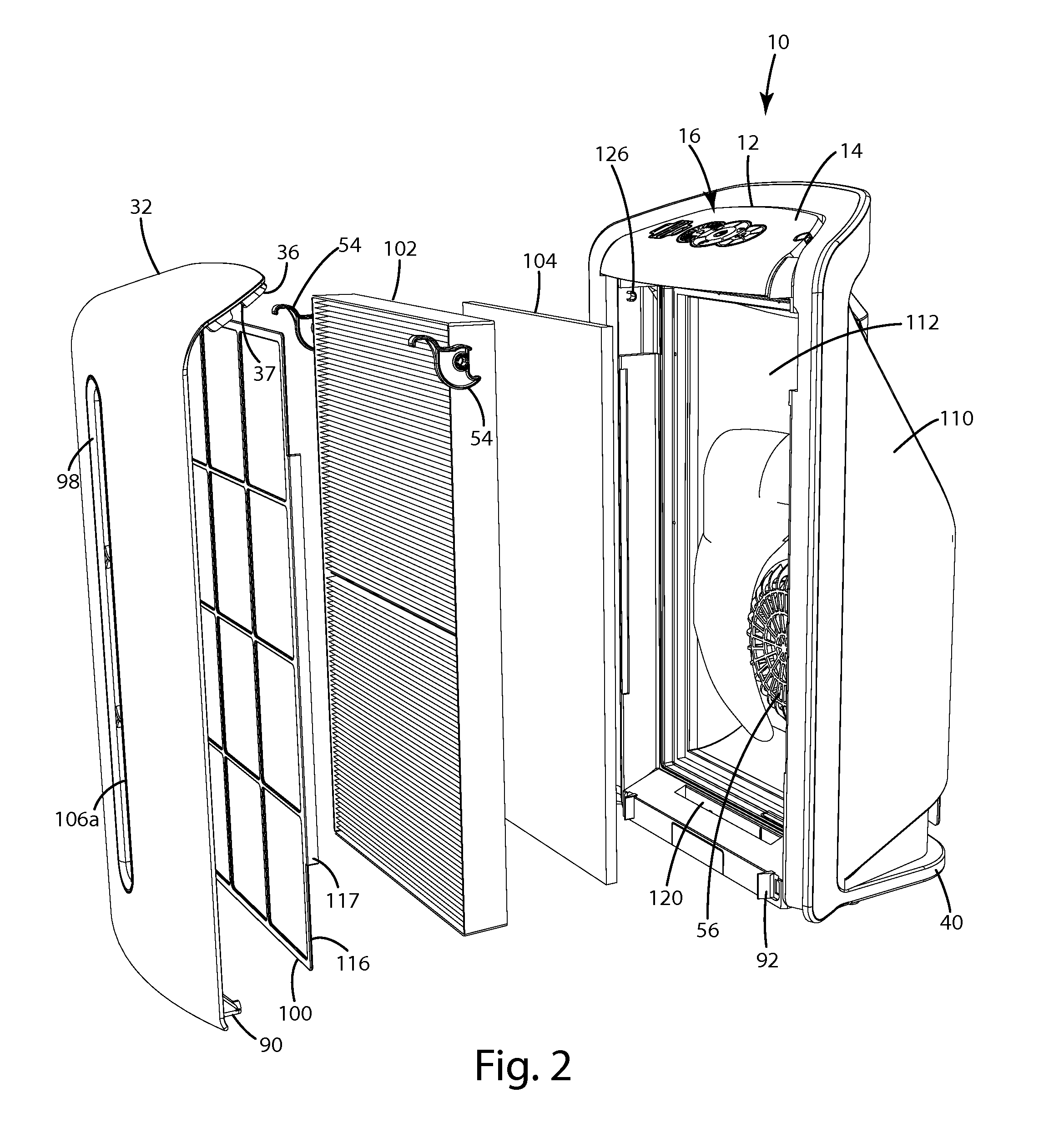
[0078]An air treatment system (“ATS”) in accordance with an embodiment of the present invention is shown in FIG. 1. The ATS 10 of the illustrated embodiment generally includes a prefilter 100, a particulate filter 102 and an activated carbon filter 104. The ATS 10 also includes a blower 56 for drawing air from the environment into the ATS 10, moving the air through the filters and returning the filtered air to the environment.

[0079]The ATS 10 of the illustrated embodiment includes a control system 12 having an electronics module 14 that provides a “dead front” display 16. The display 16 of this embodiment includes a plurality of display elements 18 that can be selectively illuminated by the control system 12 to provide dynamic content. Some of the display elements 18 may include a touch sensor 20 that allows operator input. In this embodiment, the electronics module 14 includes a plurality of light sources 22, such as LEDs, each being uniquely assigned to a display elemen...


PUM

PropertyMeasurementUnit
Coloraaaaaaaaaa
Mechanical propertiesaaaaaaaaaa
Translucencyaaaaaaaaaa

Abstract

An air treatment system having an improved control system. The control system may include a dynamic “dead front” display that varies the display based on mode of operation. The display may include capacitive touch sensors and include an array of capacitive film segments or traces integrated into the display. The control system may include a self-contained electronics module that can be tested and calibrated before installation in the ATS. A dust sensor assembly may be integrated into the electronics module. The front cover may be attached with a mechanical attachment at the top and a magnetic attachment on the bottom. The ATS may include a filter retainer assembly with a rotating clip configured to perform in a cam-like manner to firmly clamp the particulate filter and carbon filter in place.

Description

BACKGROUND OF THE INVENTION[0001]The present invention relates to air treatment systems and more particularly to a portable room air filtering system.[0002]Air treatment systems continue to grow in popularity as concerns about air quality remain an issue of significant concern. This growth has led to an increase in the use of commercial and residential air treatment systems. A conventional residential air treatment system is a self-contained unit that can be placed in a room where it is desirable to treat the air. Residential air treatment systems generally operate by drawing room air into them, treating the air with one (or more) technologies, and releasing the treated air back into the room. The treated air contains a lower concentration of airborne contaminants than in the room at large. The treated air mixes with the room air, and thus, the concentration of contaminants in the room air is reduced.[0003]Air treatment systems are available with different types of control systems. ...

Claims


Application Information

Patent Timeline
IPC IPC(8): B01D46/42B01D46/00
CPCB01D46/0023B01D46/4254B01D46/62
Inventor STONER, JR., WILLIAM T.LAUTZENHEISER, TERRY L.MORK, STEVE O.EURICH, SEAN T.NORCONK, MATTHEW J.EVANS, GREGORY K.MORCOM, JENNY L.
Owner ACCESS BUSINESS GRP INT LLC
Why Eureka
Try Eureka